| Beaver, Beaver ultralight aircraft, Beaver RX 35 ultralight aircraft, Beaver RX 550 ultralight trainer troubleshooting report. | ||||||||||||||||||||||||||||||||||
|
||||||||||||||||||||||||||||||||||
|
Give a man a fish and he will eat for a day. Teach him how to fish, and he will sit in a boat and drink beer all day. |
||||||||||||||||||||||||||||||||||
|
||||||||||||||||||||||||||||||||||
|
|
||||||||||||||||||||||||||||||||||
|
|
||||||||||||||||||||||||||||||||||
|
|
||||||||||||||||||||||||||||||||||
|
|
||||||||||||||||||||||||||||||||||
|
|
||||||||||||||||||||||||||||||||||
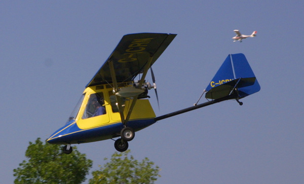
Beaver RX 35 and Beaver RX 550 ultralight aircraft. |
||||||||||||||||||||||||||||||||||
Troubleshooting the Beaver family of ultralight aircraft.If you are over forty you know the kinds of changes your body has gone through especially in the last 10 years. That daily walk to school as a teenager, now seems like a 25 mile marathon, and those weights you once could lifted easily over your head 10 times now have a difficult time reaching mid chest level. Aircraft are no different. Age, abuse, neglect, and lack of maintenance are ingredients that can spell disaster. The following is not meant to be a negative report on the Beaver family of aircraft. This report is meant to be a guide of reported problems associated with the Beaver RX 28/35/550. It can be compared to going to the doctor, having some problems identified, and then being put on a "proper diet and exercise program," which if followed can lead to a safe, long and healthy life for both the aircraft and its pilot. The Beaver ultralight became available in early 1984, and quickly became one of the fastest selling aircraft in Canada. A pilot could build the plane in less than one hundred and fifty hours, and it was priced within reach of most enthusiast adding to its popularity. (Industry sources indicate that over 2,000 Beaver aircraft have been delivered to customers worldwide.) Another feature to Canadian ultralight pilots was that it was one of the first ultralight aircraft, built in Canada that had true three axis control, cross country ability, and was available in both a two place and single seat version. Contributing to its popularity the factory sold their craft through a dealer network, which meant that many new pilots who were introduced to the Beaver later went on to purchase Beavers. The report is broken down into 5 main areas:
The Beaver factory supplied their craft with several engine options, all of them Rotax. Single seat RX 28 craft were first shipped with the single cylinder fan cooled 277, 28 HP two stroke engine. Later model RX 35 were shipped with the 377/447. The original two place RX 550 was shipped with either the 447 or 503. In early 1988 changes were made to the RX 550 engine mount and airframe which allowed for use of the 532/582 Rotax. Rotax 277Carburetor: Rotax 377/447/503A problem reported with the use of the above engines on the
Beaver has been crankshaft failures. Personal experience indicates that contributing
factors to these failures may be: When the Rotax 337/447/503 are used in an upright installation a gravity feed system is used to supply oil to the crankshaft main bearings through channels in the crankcase. While oil is still supplied to these bearings in an inverted application, it is being supplied by internal engine pressure, rather than gravity. When an upright engine, is left in storage oil flows down into the channels in the case coating the crankshaft bearings. In an inverted installation this oil flows AWAY from the bearings. This lack of oil on start up can lead to premature bearing failure. Before starting an engine that has been left in storage it is recommended that the engine be turned over for several revolutions, with the ignition turned off to bring oil back up into these bearings. 2: The use of long two blade propellers with too much pitch. This prevents the engine from developing full RPM which causes the crankshaft to be under load all the time.
3: The use of inferior oil. Remember the oil only makes up 2% of the mixture, but without this 2% the engine will not survive. So oils play an important role in engine life. Note that there are different oils for different engine application. Generally air cooled and water cooled engines do not use the same oil. Engines equipped with oil injection are also different than those used for pre-mix. Personal experience shows that many oils used in the boating industry to cool outboard engines do not work well in Rotax liquid cooled engines. Rotax does have oils that are produced to their specifications for use in both air and liquid cooled engines. Fuel Tank: Fuel pump location and mounting were also a problem on Beaver aircraft. The pump was generally mounted in front of the engine on the guard for the fan. This mounting is too far away from impulse hole! All dual carburetor engines should use a DUAL FUEL PUMP, not a single fuel pump with a "T". On the 503 Rotax SINGLE carburetor engine Rotax is now supplying the engines with a DUAL PUMP. The two output lines run into a "T" with the one line then running to the single carburetor. This an update that should be done to all 503 equipped Rotax engines. The fuel pump should be mounted ABOVE the impulse hole in the engine with the impulse fitting on the pump facing DOWN. The pump should be rubber mounted, away from heat and located not more than 12 inches from the impulse outlet on the engine. The line used to supply vacuum to the pump should be of a very thick wall (many Beaver owners have used straight gas line, which is incorrect) so as not to collapse, and all lines should be securely clamped. On early model Beavers the carburetor was reported to turn in flight. Later model engines are supplied with knurled intake manifolds and carburetors which prevent this from happening. Another reported problem by Beaver owners has been with the airfilter coming off the carburetor in flight and striking the prop. This has resulted in several fatalities! To help prevent this, it is suggested that a small hole be drilled in the back of the carb and front of the airfilter and that these holes be used to safety wire the airfilter to the carburetor. Another update has the two separate vent holes found on the sides of the carbs being replaced by one line with vent holes in the bottom. This prevents improper fuel to air mixture in the carburetor. Owners have also reported their throttle cables slipping in the retaining clamp at the throttle handle junction. In Canada many owners have reported their throttle cables freezing during winter operations. Some owners have changed the position of their ignition switches after they have applied full power, or brought power back, hitting their ignition switch and shutting their engines off. Propeller damage The Beaver family of aircraft are pushes, this means that the propeller is found at the rear of the aircraft, thus anything that exist from the aircraft in flight usually finds its way into the propeller Items that have been reported entering the prop are parts of the exhaust springs and upper and lower engine cowls. It is suggested that all of the exhaust springs be SAFETY WIRED AND THEN FILLED WITH SILICONE. This will hold the spring together if it fails. Aluminum engine cowls are starting to crack around the exhaust and intake manifolds. The fix the problem replace them with a STEEL COWL. To date I have no reports of the steel cowl failing. Another reported item that has entered the prop is the screws and washers holding the upper and lower cowls together. A dab of silicone over the washer and screws will prevent this from happening. Several owners have reported their recoil handles entering the propeller. This happens when the recoil spring looses its strength. A sign of lost strength is when the pilot has to tug on the handle several times to get the recoil rope to rewind into the recoil. Another area of concern on two place Beavers was the recoil rope guide pulleys. When these fail they cut the recoil rope and it recoils back into the housing, this of course means the owner now has to pro start the engine! Many Beaver owners using Rotax engines have reported failure of their exhaust system. These failures occur, along the welded seams of the exhaust or in one of the bends going into the muffler can, or where the exhaust connects to the exhaust manifold. These pieces can then exit into the propeller. These are a result of poor exhaust installation. While the system must be mounted securely, it still must be able to move on the exhaust sockets, and springs. Many Beaver installations are to stiff, and do not allow this movement. Rotax modified their exhaust system, to help eliminate these failures. The older two piece exhaust manifold/exhaust has been updated to a three piece unit. This unit consists of an exhaust Y pipe that feeds into a 90 degree elbow which fits into the exhaust. This helps prevent the build up of harmonic vibration in the exhaust system. Another reported problem has been with the failure of the exhaust springs. The failed springs generally end up in the propeller. This failure is a result of improper installation of the spring attachment points. The springs when installed correctly should pull straight. Many infield inspections of Beaver show that the springs are pulling at an angle and the springs are usually under too much tension. Rotax has published a bulletin giving the correct distance between these points, for each of their engine installations. Also note that there are two different springs lengths available from Rotax depending on the engine used. Install the springs hooks at the correct angle, and distance. Install the springs, safety wire the springs and then fill them with silicone. The silicone will absorb much of the vibration and if the spring fails the parts will be held together by the silicone until you can replace it. 532/582 Rotax engine One of the major problems with the use of the 532 engine on the Beaver was that of overheating. This was due to the type of radiator system used and the incorrect placement of the water temperature sending unit. To cure the overheating problem requires the installation of a new cooling system. The temperature sending unit should take its temperature from the center of the cylinder head. Another problem was with air getting trapped in the front cylinder during climb out. This could cause an engine seizure. Rotax updated the 532 water pump impeller housing. This update allows air trapped in the system to vent through the impeller housing and back into the rad system. Many owners have reported over Another reported problem was with Rotary valve shaft and seal failure. Inner seal failure can usually be detected by checking the colour of the oil in the Rotary valve tank. If a seal has failed the oil will turn a milky pink colour. Outer seal failure resulted in coolant being discharged through a vent hole located directly above the water pump impeller housing. Rotax updated this area of the 532/582 by plugging this vent hole. While this did not stop the seal failure, it prevented coolant from escaping, allowing the pilot to find and repair the problem. Both the 532 and 582 have had problems with intake manifold rubbers deteriorating and failing. These failure were reported to occur around the bolts securing the intake rubber to the engine on the 532 and directly around and underneath the securing clamps on the 532/582. In 1987 Spectrum aircraft manufacturers of the Beaver sent a notice out relating to electric starters supplied by ADS. Apparently the starters were incompatible with some models of Rotax engines. The starters were apparently were misaligned between the starter and crankshaft flywheel which apparently caused "catastrophic engine failure without warning." If you are using an ADS starter (no longer in production) it is suggested this be area of regular inspection. The standard reduction drive supplied on the Beaver is a Rotax gear drive system. Beaver owners have reported failures of this drive, as well Rotax has updated the drive several times over the years. Failures and updates include: Failure of the bolts securing the drive to the engine. The drive system used on the Beaver is secured by either 3 or 4 bolts depending on the year of the aircraft. These bolts have been reported to come loose and or fail. It is suggested that when installing the bolts that BLUE LOCTITE be used on the threads of the bolts, and that these bolts be an area of regular inspection. Rotax has also updated the drive from a three bolt system to a four bolt on older engines, while newer CDI equipped engines have a 6 or 8 bolt retaining system. Failure of the drive gear. Numerous owners have reported failure of the large gear used in the Rotax B gear box. Early model drives had a gear that was full of holes. New gears are solid. Several owners have reported failure of the dog hub which is used to transfer the power from the gear to the output shaft. Rotax has updated this dog hub from a two fork system to a four fork system. The four fork system is also quite a bit beefier. Failure of the Spring washers. Many owners have reported problems with hard starting engines. Rotax traced this problem to weak spring washers located on the output shaft below the dog hub. The solution to the problem was change from the old 8 washer system to the new 12 washer system. Failure of the drive output shaft. Several owners of older aircraft have reported failure of the aluminum hub found on the output shaft which the prop bolted onto. Rotax updated both the output shaft and hub. New shafts have a steel flange which is part of the shaft rather than a separate unit. Loss of gear oil from drive resulting in gear box failure. Many Beaver owners have reported gear box failure. This failure was traced to lack of lubrication. It was found that the pressure build up inside the gear box, along with the siphoning action of the propeller would suck the oil out of the gear box. Rotax found that an oil slinger, located on the end of the crankshaft, used to fling the oil around inside the drive was causing to much pressure build up. Part of the solution was to remove this slinger. Rotax has also updated the vent cap on the drive to help eliminate the siphoning action. Failure of the bolts securing the prop onto the reduction drive. A problem that has caused several fatalities on Beaver aircraft has been prop retaining bolt failure. To date all reports that I have were using two blade wooden propellers. A solution was to switch to a GSC propeller. The GSC uses dowel pins in the larger holes located on the drive. These fit into holes in the propeller hub and prevent stress being passed back onto the prop bolts. Other solutions that have been reported to work are the use of shorter three blade propellers, especially props like the IVO prop which are much lighter. Rotax has recently updated their drives so that the smaller holes are no longer threaded. This means that the bolts now require a nut and washer to secure the prop to the flange, which helps eliminate over torquing of the bolts and the stripping of the threads in the output shaft flange. This update can be done on older drives by carefully drilling out the holes and replacing the bolts, with a bolt nut and washer. The Beaver airframe, uses aluminum tube, bolt together construction. While this type of construction makes for quick and easy building times, it has also shown itself to be a system that will show its age quickly if abused, or neglected. The type of suspension used on the Beaver uses a shock absorber system. Owners have reported failure of the shock absorbers after a hard landing, or on cross wind landing. This is an area that should be inspected closely before each flight. Another area of reported failure is the axle assembly. It has been reported to fail where the bolts for the mounting plates for the shocks are located.. These axle arms have also been reported to crack and break where they are crushed at the top. One solution was to update the gear to a chromoly system. This system is produced by Back Forty Developments in Campbellford Ontario, and is available for Challenger aircraft as well. The nose wheel support tubes Failure of the nose wheel support tubes have been reported. The proper solution requires the replacement of worn or damaged support tubes with new. Owners have reported loosing wheels on landing of their craft. This is apparently due to the wear on the roll pin used to retain the wheel on the axle shaft. In some cases this is due to the incorrect installation of the wheel. There should be a large flat washer between the wheel and the roll pin. This helps prevent excessive wear on the pin. The horizontal stabilizer jury struts. Wear has been reported at the end of the horizontal stabilizer support tube where it connects to the main boom. This wear is caused by vibration. If wear is apparent the rivets should be removed the bracket and boom inspected any damaged parts repaired or replaced. In late 1989 several owners reported failure of the main root tube on Beaver aircraft. These failures apparently occurred aft of the trailing edge spar bracket. Reports of "hairline fractures propagated around the square tubing at the cantilever point for the engine." Beaver RX Enterprise recommended "immediate inspection of the root tube on all aircraft with inverted engine mounts. Especially the area around the rear down tube pickups to the forward edge of the engine mounts." They update this area of the craft by installing a 1/8" wall sleeve (a round inner sleeve) into the square root tube. Another area of reported failure on the RX28/35/550 series of aircraft was the wing attachment brackets (#2986). These apparently were originally aluminum brackets, and were updated to a steel bracket. Failure of the motor mount bracket on the RX-550 RSU was also reported at the junction of the tubes and gusset plate. Owners have also reported failure of the Foot support tube. Failure occurs at the top of the tube where it attaches to the square tube. Spectrum aircraft indicated that they felt that this failure was caused due to rough field use, improper propeller alignment and or balance, and fatigue. Their recommendation was to inspect this area every preflight and to replace the tube (#2612) every 100 hours. This area was also the subject of an update. Elevator cables: Action: All operators are requested to pay special attention to the cables at the point where they go around the pulleys. Cables should be checked on every pre-flight with special attention given at the beginning of each day or flying session. It is mandatory that the cables be replaced after 2 years or 200 hours, whether they show signs of deterioration or not. Boom tube fatigue: Two areas of fatigue or failure have been reported on the Beaver line of aircraft. One area is at the vertical stab post bolt attachment point. The other directly below the engine on the main boom. The manufactures recommended that "stop drilling" be used to prevent further cracking of the main tube at the vertical stab post. Jury strut failure: Owners report failure of the jury struts at the jury strut wrap around. This should be an area of regular inspection. The jury strut bracket #959 and #2959 operate under tension loading during flight and the forces are more concentrated at the front side struts. Installation of the brackets using needle nose pliers may scar the edge of the bracket weakening it. Pre-flight of the bracket should concentrate on the area between the rod end and the strut. Should there be any indication of scarring then the brackets should be replaced. If the rubber insulator for the bracket is to large a diameter it is suggested that black electrical tape be used to as a wrap to the proper diameter. Rudder cable failure: Owners report failure of the rudder cables (#2416-02) on model RX 550 aircraft. The cables are apparently fraying. This should be an area of regular inspection. The following in advisory #028 issued by the builders of the Beaver As a result of information received from operators and constructors of Spectrum products and as a result of a major overhaul carried out on an RX 550 with 590 hours time since new the following technical highlights have been compiled. 1. As a result of turning the rudder horns to clear the horizontal stabilizer struts there has been a problem on tail wheel equipped aircraft with the tail wheel side plates contacting the underside of the rudder horns and restricting free movement of the rudder. This can be reminded by placing AN970-4 washers between the plug and the swivel block. Use the minimum number of washers required to gain clearance. Increase the length of the 1.4" bolts by 1 dash number for every 2 washers installed. 2. Addition security can be gained on landing gear by using 2 stainless steel tangs on each end of the drag struts. This provides back up in the event of failure of the tang. It does not double the strength of the joints but provides additional protection for aircraft, occupants and parachute. 3. All seat belts and seat belt attachment hardware should be replaced after any major accident, etc. and should be replaced after 500 hrs in service as a matter of course. 4. The front seat mounting brackets have, on training aircraft been found to be collapsing into the control stick connector pushrod. All operators are advised to monitor the condition of the bracket and replace it before it can contact and interfere with the push rod. One of the reasons for the Beavers popularity is its quick build time. This is a result of using dacron sailcloth. This fabric if left unprotected, can loose 90 per cent of its strength in as little as a year. Check the colour of your fabric! The wings fabric colour should be the same colour top and bottom. If the top side of the wing is faded, compared to the underside it should be checked using a Maule tester or the "Quicksilver" tester. For more information on how to properly test the fabric contact someone knowledgeable in the industry such as L'il Hustler Aviation LEAF/CPS Gunnar Sails etc. Two ways of protecting the fabric include using a UV resistant paint barrier, or applying Stits A0-100 which is a clear coat which goes over the fabric. On Beaver RX 550 aircraft flown with rear shoulder harnesses: Several owners have reported their shoulder harnesses coming in contact with the propeller, when they have inadvertently left them undone. It is recommended that some kind of retaining strap be installed to prevent this from happening. Wing bracing wire failure: Several fatalities on Beaver RX 550 have been traced to the failure of the wing bracing cable. This cable runs from one end of the wing to the sleeve used to secure it at the strut attachment point. It is recommended that this be an area of immediate inspection. Owner should use a nico sleeve measure tool to verify that their nico sleeves have not elongated and were properly pressed at the factory. According to knowledgeable people in the industry a way of fixing the problem is to disassemble the wing and replace the one length of cable with separate cables for each wing panel securing them at each compression strut. This is not something that the average person should attempt! The following is based on a Transportation Safety Board of Canada - Engineering Report LP 44/93 Incident Report: An instructor and student were practicing stalls and stall recoveries. During a sequence, the left hand wing separated from the aircraft, the aircraft crashed, and both occupants were fatally injured. A detailed structural analysis was conducted. That analysis raises concerns about the use of Nicopress stop sleeves in securing the drag truss. Examination and Analysis. Figure 3 is a photograph of the first stop sleeve. This sleeve was loose, and could easily be moved by hand. The cable on one side of the sleeve contained some copper coloured residue, which was considered to have come from the sleeve, suggesting that the sleeve had previously slid along the cable. There was also some white residue of what was considered to be teflon from the end cap of a compression rib. Figure 5 is a photograph comparing one of the sleeves installed by the Nicopress manufacturer with one of the sleeves recovered from the crashed aircraft. Comparison suggests that the sleeve from the accident aircraft was not installed using the correct tool. The one sleeve from the accident aircraft which had not yet slipped was also tested. It was able to react a force of only 393 lbs. Figure 7 is a photograph of the assembly after the test. The mode of failure was such that there was no damage to the cable, but the sleeve slipped along the cable leaving a trail of copper coloured residue. Two of the specimens installed by the Nicopress manufacturer were tested. Both failed at 800 lbs tension, exceeding the rated strength of 600 lbs. The mode of failure was such that the sleeve did not slip, but rather strands of cable started to break in the vicinity of the sleeve. Conclusions: The structural integrity of the wing in the drag plane depends on the gripping strength of the stop sleeves in the corner of each bay. Although the correct stop sleeves had been used, it was considered that they were installed using the incorrect tool, which resulted in a lower gripping strength. The most heavily loaded stop sleeve in the structure had a gripping strength of 60% of its rated value. The most common method of anchoring the drag truss in an aircraft wing has two lengths of cable, with each end firmly anchored to a corner. The RX 550 is made up of only two cables, which zig-zag through the wing, and are anchored in the corner of each bay by a Nicopress stop sleeve. In order for this method to work, the stop sleeves must be able to react sufficient force that they do not slip. If they do slip, the wing will collapse in the drag plane. Click below for a Full View of problem area ! |
||||||||||||||||||||||||||||||||||
|
|
||||||||||||||||||||||||||||||||||
|
||||||||||||||||||||||||||||||||||
| Ultralight Aircraft News Web Magazine Covering the World of Ultralight Aviation. You may link to these pages or print them out for your own personal use, but no part of this publication may be copied or distributed, transmitted, transcribed, stored in a retrieval system, or translated into any human or computer language, in any form or by any means, electronic, mechanical, manual, or otherwise, without the written permission of Ultralight News. By copying or paraphrasing the intellectual property on this site, you're automatically signing a binding contract and agreeing to be billed $10,000 payable immediately. Copyright Ultralight News | ||||||||||||||||||||||||||||||||||
| Return to Main Index for this section | ||||||||||||||||||||||||||||||||||
