   Operator's Manual
Engine
2702
Göbler-Hirthmotoren KG, Max-Eyth-Str. 10, D-71726 Benningen
Tel.: 07144-8551-0, Fax: 07144-5415
Distributed by AATI Pty Ltd, Aircraft & Agricultural Tillage Importers
e-mail: info@aati.com.au, internet: http://www.ultralightnews.ca/
Phone Australia: (07)5464-4993, Fax: (07)5464-4995
Phone International: +61 7 5464-4993, Fax +61 7 5464-4995
|
 Operator's Manual
Engine
Model 2702
Read this operator's manual thoroughly before putting the engine into operation for the first time and comply
strictly with the instructions given here.
In the interests of continual development of our engines we must reserve the right to change conditions of
delivery for design, engineering and fixtures. We also request your understanding that no claims can be made
against statements and Figures from this manual.
THIS ENGINE DOES NOT COMPLY WITH FEDERAL SAFETY REGULATIONS FOR
STANDARD AIRCRAFT. THIS ENGINE CAN BE USED IN EXPERIMENTAL AND ULTRA-
LIGHT UNCERTIFIED AIRCRAFT ONLY IN CIRCUMSTANCES WHICH AN ENGINE FAILURE
WILL NOT COMPROMISE SAFETY. BEFORE OPERATING THE ENGINE READ OPERATOR'S
MANUAL INFORMATION AVAILABLE FROM YOUR AUTHORISED HIRTH DISTRIBUTOR.
Göbler-Hirthmotoren KG
|
 1Description of the Engine, Mounting Instructions and Technical Data.....................................................5
1.1Overview...........................................................................................................................................5
1.2Description of the carburation system...............................................................................................5
1.3Description of the Ignition System....................................................................................................6
1.4Description of the cooling system......................................................................................................7
2Installation instructions..............................................................................................................................8
2.1Mounting and securing the engine.....................................................................................................8
2.2The engine?s air supply......................................................................................................................8
2.3The engine?s fuel system and fuel supply..........................................................................................9
2.4The operation of the single carburettor..............................................................................................9
2.5Securing the spark plug leads in a hanging (inverted) installation...................................................10
2.6Switching off the Ignition System (dual ignition)............................................................................10
3Monitoring Apparatus..............................................................................................................................11
3.1Cylinder head temperature...............................................................................................................11
3.2Exhaust gas temperature..................................................................................................................13
3.3Fuel Pressure...................................................................................................................................15
3.4Model Identification plate...............................................................................................................15
3.5Specifications ? 2702 engine...........................................................................................................16
3.6Installation Drawing - 2702.............................................................................................................16
4Operation of the Engine...........................................................................................................................17
4.1General............................................................................................................................................17
4.2Running in - Recommendation........................................................................................................18
4.3Initial Inspection..............................................................................................................................18
4.4Starting Procedure...........................................................................................................................18
4.5Operating condition of the engine....................................................................................................19
4.6Powering down the engine...............................................................................................................19
5Maintenance............................................................................................................................................20
5.1General............................................................................................................................................20
5.2Tools, special tools and torques.......................................................................................................20
6Maintenance rate.....................................................................................................................................21
6.1Daily inspections.............................................................................................................................21
6.2Periodic Inspections.........................................................................................................................21
6.3Replacement of Parts.......................................................................................................................22
7Maintenance instructions.........................................................................................................................22
7.1Carburettor.......................................................................................................................................22
7.2Inspecting the air filters...................................................................................................................22
7.3Inspecting the fuel lines...................................................................................................................22
7.4Inspecting pulsation lines.................................................................................................................22
7.5Spark plugs and sparkplug leads......................................................................................................22
7.6Inspecting the condition of the sparkplug leads...............................................................................23
7.7Installing and removing sparkplugs.................................................................................................23
7.8Condition of the sparkplug..............................................................................................................23
8Fan...........................................................................................................................................................23
8.1Remove and assembling the air cowl...............................................................................................23
8.2Remove and assembling the fan housing.........................................................................................23
8.3Changing the fan belt.......................................................................................................................23
9Cylinder head...........................................................................................................................................24
9.1Cylinder head removal and installation...........................................................................................24
9.2Checking the condition of the cylinder head....................................................................................24
10Trouble Shooting.............................................................................................................................25
10.1Engine Does Not Start or is Difficult to Start..................................................................................25
10.2Engine will not Idle.........................................................................................................................25
10.3Engine Runs Rough, Uneven, and with Insufficient Power.............................................................25
10.4Engine Does Not Develop Full Power.............................................................................................25
10.5Excessive Cylinder Head Temperature............................................................................................26
11Exhaust System................................................................................................................................27
11.1Exhaust parts and measurements.....................................................................................................28
12Wiring Diagrams.............................................................................................................................29
|
|
12.1Single PVL Ignition system - 2702..................................................................................................30
12.2Dual PVL ignition system ? 2702....................................................................................................31
|
 http://www.ultralightnews.ca/ Page 5 of 31
The Ultralight News - your one stop shop!
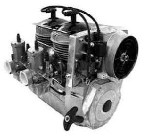
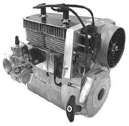
1Description of the Engine, Mounting Instructions and Technical Data
1.1Overview
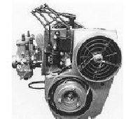
The 2702 engine (Figure 1.1.1-1) of Göbler-Hirthmotoren KG is a two cylinder in-line two-stroke engine
available with a ducted cooling system or a free air ducted cooling system.
The cylinders consist of an aluminium alloy with a Nikasil coated running surface that is highly resistant to
wear. The cylinders are mounted onto the crankcase by stud bolts, discs and hexagon nuts. The cylinder
heads consist of a special hypereutectic aluminium alloy that resists high temperatures while maintaining
constant hardness. They are secured onto the cylinder by means of cylinder screws and washer without using
agasket to assist cooling.
The pistons consist of an aluminium alloy and are sealed off from the cylinder running surface by two piston
rings. The piston is connected to the con-rod by the gudgeon pin and a needle bearing.
The crankshaft is made of chrome-molybdenum steel (42 Cr Mo 4) and is mounted in five deep groove ball
bearings. It?s really an assembled crankshaft and the individual parts of the crankshaft are pressed together to
form a complete unit. Two deep groove ball bearings are installed on the drive side, two between the con-
rods and one on the ignition side. The drive shaft is tapered and has a centred thread in order to secure to the
PTO shaft. The con-rods are connected to the crankshaft by crank pins and needle bearings.
The crankcase consists of an aluminium alloy and constructed as a case in two halves. It is secured together
by seven bolts and eight fastening studs and nuts which secure the cylinders to the case. Opposite the PTO
end of the crankcase, there is an ignition stator unit. This is fixed to the crankcase and is concealed by the
flywheel and the fan housing..
Figure 1.1.1-1 (Engine 2702)
1.2Description of the carburation system
The carburation system (Figure 1.1.2-1) of the 2702 engine consists of one Mikuni variable jet carburettor.
The carburettor is connected to the inlet aperture of the cylinder by a rubber flange and is secured to the inlet
aperture by means of a clamp held in a rubber flange. It is thermally neutralised from each cylinder by an
insulating plate thereby shielding the carburettor from the hot air exiting from the cooling system. The
carburettor has a dry air filter installed.
|
  http://www.ultralightnews.ca/ Page 6 of 31
The Ultralight News - your one stop shop!
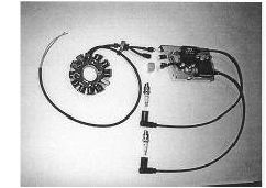
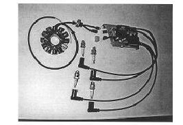
1.3Description of the Ignition System
The ignition system (Figure 1.3-1, 1.3-2) consists of a armature plate, a magneto, E-Box(s), ignition coils and
the ignition cables with the required number of spark plug leads. The ignition system is completely electronic
and possesses an E-PROM for a freely programmable ignition curve however, this can only be carried out by
the manufacturer. Alternating Current (AC) power for electrical components during running and charging of
the battery is provided. The engine is available with a single or dual ignition system installed.
An electronic stator plate is secured on the ignition side with the crankcase. A magneto is fixed on the
crankshaft and encloses the armature plate. The fan housing covers the ignition system?s magnetic wheel.
The electronic E-box and ignition coils are mounted on a fixture plate secured to the crankcase as shown in
figure 1.3.3.
Figure 1.3-1 (Single PVL ignition)
Figure 1.1.3-2 (Dual PVL ignition)
|
  http://www.ultralightnews.ca/ Page 7 of 31
The Ultralight News - your one stop shop!
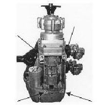
Figure 1.3-3
(View of ignition side with installed ignition system)
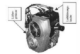
1.4Description of the cooling system
The 2702 engine has a mechanically operated forced fan cooling system. (Figure 1.4-1).
The fan wheel is installed in the fan housing. It is driven by a flat belt and a pulley that is fixed to the
ignition system?s magnetic flywheel. A stream of cool air generated by the fan is distributed for optimal
cooling to the two cylinders. The hot air stream from the cooling system is blown off to the opposite side of
the engine into the surroundings on the intake side.
Figure 1.4-1 (View of the fan housing and the air conduction cowl)
|
 http://www.ultralightnews.ca/ Page 8 of 31
The Ultralight News - your one stop shop!
2Installation instructions
2.1Mounting and securing the engine
The four screw threads (UNC- ½?) on engine 2702 for the fastening of the engine are located on the
underside of the crankcase.
Figure 2.1-1(Fastening thread points)
The engine should be mounted so that the moment from the engine to the mounts can be absorbed as widely
as possible. The absorbing of the mounts should also be made as hard as possible, since the engine can
become unstable if the absorbing mounts are too soft. This leads to problems within the carburettors fuel
bowl as well as uncontrolled vibration of the fuel pump diaphragm, intimating to an unsafe operation of the
engine.
-Suggestion for securing the engine:
The engine is secured to a fastening plate that is about twice the width of the engine (the wider the better).
On the two outer surfaces of the fastening plate six (or more) hard rubber absorber elements (three on each
side) are attached in an axial direction. This complete substructure is secured by the rubber absorber
elements on to a corresponding base plate.
2.2The engine?s air supply
The engine must be installed so the cooling air stream fed to the engine is sufficient to ensure the engine is
cooled and that air is also supplied to the carburettors.
With an enclosed installation it is important that the hot outlet air stream is not fed to the carburettors, as this
leads to a drastic reduction in performance. It is also important to ensure that the hot outlet airstream can
escape with out hindrance from the metal cladding, since this leads to overheating of the engine and also
damage.
The ducted cooling system fixed to the motor is designed so that adequate supply of fresh air for cooling of
the engine is sufficient. Changes to the cooling system therefore are not recommended. It is essential to
ensure that a sufficient supply of air is provided at all times during operation.
|
 http://www.ultralightnews.ca/ Page 9 of 31
The Ultralight News - your one stop shop!
2.3The engine?s fuel system and fuel supply
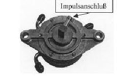
The engine?s fuel supply is provided by a Mikuni diaphragm pump (Figure 2.3-1) that is driven by pressure
pulsation from the crankcase.
Figure 2.3-1 (Fuel-diaphragm pump with impulse connection)
This diaphragm pump is positioned in the fuel line between the fuel tank and the Mikuni carburettor. A fuel
filter should always be installed between the fuel pump and fuel tank.
The Mikuni fuel pump should be secured to a location with the least influence of vibration or heat. It is
important that it is installed upright with the fuel outlet at the top. The assignment of the fuel connection
direction can be identified on the housing by arrows.
The central connection of the Mikuni pump is connected to the vacuum impulse line from the crankcase and
should be as short and straight as possible. When choosing the impulse line and the fuel line it is important to
ensure that rigid lines are used and do not expand under pressure. The impulse line should not exceed a
maximum length of 150mm with a minimum inner diameter of 6 mm.
The positioning of the fuel tank over the engine is advantageous as would ensure a reasonable fuel supply
pressure. It is recommended to maintain a constant fuel pressure under all conditions with sufficient fuel in
the fuel tank. Additional monitoring of fuel pressure by means of a fuel pressure gauge may also be
considered.
When installing the fuel tank beneath the engine, the maximum fuel line length between the fuel tank and
diaphragm pump should not exceed 2,000mm. The maximum suction head should not exceed 1,000m with a
minimum inner diameter of 6mm.
Be aware of the possible gradient of the vehicle the engine is installed in during operation i.e. ascent-/descent
with aircraft, uphill-/downhill with ground vehicles.
The maximum length of the fuel outlet pressure line should not exceed 500 mm with a minimum inner
diameter of 6 mm. A maximum pressure head between the centre of the diaphragm pump and centre of the
carburettor float chamber may not be exceeded.
If a Mikuni pump is installed on the engine, it is recommended the diaphragm of the pump stands vertical to
the crankshaft axis (drive or ignition side ). This will ensure that resonance produced by the crankshaft axis
from the engine does not impair the action and function of the fuel pump.
2.4The operation of the single carburettor
The throttle valve of the carburettor is operated via a Bowden type cable. There should be enough play in the
cable to ensure that the throttle valves can reach the idle position stop.
|
|
http://www.ultralightnews.ca/ Page 10 of 31
The Ultralight News - your one stop shop!
2.5Securing the spark plug leads in a hanging (inverted) installation
If the engine is installed in a hanging or inverted position, the sparkplug leads should be secured so that any
breaking or interruption of contact by engine vibrations is prevented (support or secure by wires).
2.6Switching off the Ignition System (dual ignition)
It is essential that both ignition circuit breakers are located on separate grounding switches. It is important
each earthing wire is installed separately to avoid circuit failure. This method also aids the operator to check
each ignition side when the engine is operating.
|
  http://www.ultralightnews.ca/ Page 11 of 31
The Ultralight News - your one stop shop!
3Monitoring Apparatus
It is recommended that the cylinder head temperatures, the exhaust gas temperature and the fuel pressure be
monitored.
The basic setting of the engine guarantees a problem free-engine function under the general installation
conditions. It is very important for safe running of the engine that the cylinder head, exhaust gas temperature
and the fuel pressure are monitored.
The equipment listed in Table 3-1 can be purchased from AATI Pty Ltd or your Hirth distributor.
Table 3-1
Description Part No.
Westach Exhaust gas temperature measuring device (2x, as a set) 029.30
Westach Cylinder head temperature measuring device (2x,as a set) sparkplug 14 mm 029.31
Westach Cylinder head temperature measuring device(2x, complete) sparkplug 10 mm 029.32
Westach Fuel pressure measuring device 029.20
Westach Tachometer 029.14
3.1Cylinder head temperature
To allow for expansion of the piston in an air cooled engine, the tolerance between the piston and the
cylinder wall is essential for expansion and contraction. As the piston and cylinder heat under normal
operating conditions they expand, the piston becomes "larger" while at the same time the cylinder walls
expands. Engine manufactures allow for this "expansion" and "contraction" when they produce the engine.
Normally a Hirth air cooled engine should read between 350F to 410F on a cylinder head temperature gauge
(CHT). When an engine overheats the amount of expansion between these parts is greater than allowed - the
piston becomes too tight in the cylinder and the piston "seizes' creating permanent damage to the piston and
or cylinder wall
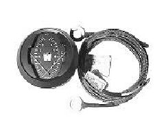
Figure 3.1.1 Dual Westach CHT 029.31/029.32
AWestach CHT (Figure 3.1) gauge uses a Type K thermocouple, which requires no power. The
thermocouple produces a small voltage which to work properly requires good continuity to reach the
instrument
The thermocouple, which is available in two different sizes depending on the spark plug used - is mounted
under the spark plug, and replaces the spark plug washer.All of the Hirth two cylinderengines use a
10mm or a 14mm probe.
|
  http://www.ultralightnews.ca/ Page 12 of 31
The Ultralight News - your one stop shop!
CHT temperatures in excess of 280°C or 536°F are a result of :
Lack of oil in fuel or NO oil in the fuel.
Poor piston cylinder lubrication, due to poor quality of oil.
The use of a fan belt other than that supplied by Hirth, a loose, or damaged fan belt.
Ablocked fan intake duct, or blocked cylinder head fins. (Insect nesting, mice etc.).
Insufficient cooling due to air intake design.
Pre-ignition or detonation, caused by old fuel, improper octane, ignition timing.
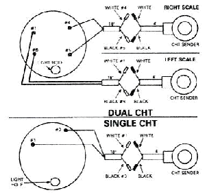
Figure 3.1.2 Installation wiring diagram
|
  http://www.ultralightnews.ca/ Page 13 of 31
The Ultralight News - your one stop shop!
3.2Exhaust gas temperature
Agauge that we recommend on all Hirth two stroke engines is the Westach Exhaust Gas Temperature gauge
(EGT) as in figure 3.2.1. This gauge is a reliable measurement tool that measures the exhaust gases as they
exit the engine. A rich fuel/air mixture which can be caused by improper jetting, clogged air filter, improper
prop setting, will generally show up as a cooler temperature. A too lean mixture can be caused by an air leak
or fuel blockage, can result in overheating and engine seizure.
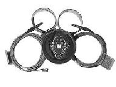
Figure 3.2.1 Westach Dual EGT 029.30
The proper location of the EGT probe on the exhaust manifold is extremely important. Mounting the probe
too close or too far from the piston will result in an incorrect reading.
If the engine is installed with one carburettor, the probe needs to be located in the centre of one of the
exhaust manifold ports 85mm from the exhaust outlet of the engine cylinder exhaust port Install the probe
before reinstalling the manifold and make sure the probe will not touch the other side of the manifold wall.
The 50mm round EGT the gauge will mount from the front of the panel and will require a 52.388mm round
hole, a U bracket holds it in place from the rear.
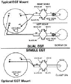
Figure 3.2.2 Exhaust gas temperature wiring diagram
|
 http://www.ultralightnews.ca/ Page 14 of 31
The Ultralight News - your one stop shop!
The EGT gauges require probes which come with 100mm of lead. To install the probe, drill a 4.763mm hole
in the centre of the exhaust pipe at the recommended distance above. Install the probe into the hole, and
tighten up the clamp. As an option, manifolds are provided to suit the "bayonet probe" type. The terminal
cable can be lengthened to a maximum of 4.5 metres without affecting the accuracy of the instrument.
Route all wires away from the manifold and other heat sources. Support the wires every 300mm intervals,
using tie wire or similar. When going through firewalls etc, use rubber grommets to prevent damaging the
wiring. Do not route these wires with any wires from an AC source, such as a lighting coil, spark wires, tech
wires, etc. The EGT operates on .004 millivolts. Running near an AC source will result in incorrect
readings.
It is important that you verify the EGT readings by careful examination of the spark plugs. A reading on an
EGT of 1100 to 1200 degrees F should give a nice tan coloured spark plug. Lower readings should give
darker colours while higher readings grey/white colours.
Once you have verified a spark plug colour and seen where your gauge reads with the proper colour then it is
now more important to watch for a CHANGE in the gauge reading from this "normal reading."
It is important to set your engine up for proper fuel to air mixture, your EGT gauge and probes can aid in
doing this. A lean mixture will run hotter on the EGT. A rich mixture will run cooler on the EGT but will
make increasingly less power. Ideally the highest EGT temps should come in at settings usually 5200 to 5800
rpm.
Reason for EGT temperature changes include:
Air intake leak.
Air fuel mixture too lean
Air fuel mixture too rich
Changes in density altitude
Changes in relative humidity
Changes in air temperature
Pre-ignition or detonation
Fault spark plug or ignition system
Improper prop load
Poor quality or grade of fuel
Improper fuel air ratio, plugged main jet, failed needle jet, or clip
|
  http://www.ultralightnews.ca/ Page 15 of 31
The Ultralight News - your one stop shop!
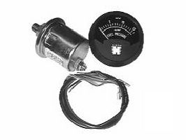
3.3Fuel Pressure
As mentioned previously, it is recommended to maintain a constant fuel pressure under all conditions.
Additional monitoring of fuel pressure by means of a fuel pressure gauge may also be considered. One such
suitable gauge is manufactured by Westach and is available for pressure of 16psi and 80psi.
Figure 3.3.1 Westach fuel pressure gauge 029.20/029.21
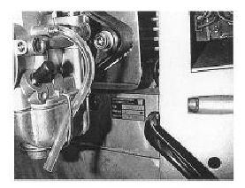
3.4Model Identification plate
The model plate is attached to the intake side on the upper part of the crankcase This also includes the serial
number of the engine and must be quoted should a warranty claim be required.
Figure 3.4-1 (Position of the Model Plate)
|
  http://www.ultralightnews.ca/ Page 16 of 31
The Ultralight News - your one stop shop!
3.5Specifications ? 2702 engine
Table 3.5-1
Manufacturer Göbler-Hirthmotoren KG
Model 2702
Operating mode Two stroke
Number of cylinders Two in line
Piston Capacity 521 cm
3
Stroke Length 64 mm
Bore 72mm
Compression ratio 9.5:1
Performance 29.4 kW (40 HP).
RPM, max. 6500 rpm
Direction of revs Left, looking towards the drive shaft
Starter Electric Starter and/or Recoil Starter
Ignition System Electronic Characteristic Ignition, single or dual
Generator 250 W, 12 V
Sparkplugs BR 8 ES (NGK) WR 4 CC (Bosch), W 24 ERS (ND)
Ignition Timing 16v. OT (at 2000 rpm)
0
Carburation 1 Mikuni VM 34-389-1, 1 Air filter
Cooling Fan Cooling, directly driven via flat belts
Mixing 1:50
Fuel Premium unleaded, 95 Octane
Two Stroke oil Branded two stroke oil for hot (air-cooled) engines
Cylinder head temperature Max 280C/536F
00
Exhaust gas temperature max 680C/1256F
00
Fuel pressure min. 0.3 bar / 5.8 psi
Engine weight without exhaust System 31kg / 70.88lbs
Weight of exhaust system 6 kg / 7.33 lbs
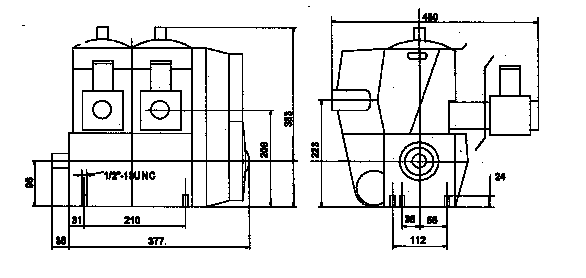
3.6Installation Drawing - 2702
|
 http://www.ultralightnews.ca/ Page 17 of 31
The Ultralight News - your one stop shop!
4Operation of the Engine
4.1General
It is important to observe the instructions provided in this chapter in order to maintain a safe and economical
operation of the engine.
USE ONLY THE PRESCRIBED TYPE OF TWO STROKE OIL AND THE PROPER GRADE
OF FUEL.
INSURE THAT FUEL IS MIXED IN THE CORRECT GAS/OIL RATIO. REMOVE THE FUEL
FROM THE CARBURETOR BOWLS AND FUEL TANK WHENEVER THE ENGINE IS NOT
GOING TO BE USED FOR AN EXTENDED PERIOD. AFTER A LENGTHY STANDDOWN,
REMOVE ANY LEFTOVER FUEL IN CARBURETOR BOWLS AND FUEL TANK BEFORE
OPERATING THE ENGINE.
TAKE CARE THAT THE AIR CIRCULATION IS SUFFICIENT TO COOL THE ENGINE AND
SUPPLY THE CARBURETORS.
INSURE THAT THERE IS NO OBSTRUCTION THAT CAN IMPEDE THE EXIT OF HOT
AIR.
ENSURE THAT HEATED EXHAUST AIR FROM THE COOLING SYSTEM IS NOT SUCKED
INTO THE CARBURETORS.
USE ONLY RESISTOR TYPE SPARK PLUGS AND RESISTOR PLUG CAPS.
ALWAYS ALLOW THE ENGINE A WARMUP AND COOL DOWN PHASE:
|
 http://www.ultralightnews.ca/ Page 18 of 31
The Ultralight News - your one stop shop!
4.2Running in - Recommendation
Göbler-Hirthmotoren KG does not give explicit instructions for running in its engines, since the
nickel-silicium coating of the cylinder and the aluminium pistons do not have to wear to each other. The
engines are ready for full throttle from the time they are built if the maximum temperatures of the cylinder
head and exhaust gases mentioned earlier are not exceeded.
However, it would be wise when the engine is first started, to run the motor at half throttle and load (not over
4000 rpm) for the first hour of operation. Please note, the engine has been initially run at the factory to set the
electronic timing so it is possible when the engine is first started, there may be more smoke than usual. This
is generally due to excess oil possibly still in the engine during assembly and will reduce to normal after the
engine has been running for a couple of minutes.
4.3Initial Inspection
After the first 10 - 15 hours in operation or after a large service the following service tasks should be carried
out:
-Tighten the engine fitting screws as a safety measure
-Re-torque the cylinder head screws as a safety measure
-Tighten the sparkplugs as a safety measure
-Visual check (leakage, loose nuts/screws etc.)
Note:
It is recommended that the following inspection be carried out for safety reasons before each use of the
engine:
Starter (check connections, fitting and condition)
Carburettors (check connections, fixtures and condition)
Ignition system (check connections, fitting and condition)
Air cooling system (check fitting and condition; check fan belts for condition and tension)
Cylinder head (check connections, fitting and condition)
Cylinders (check fixtures and condition)
Exhaust gas manifold (check fitting and condition)
Exhaust system (check fixtures and condition)
Sparkplugs and sparkplug leads (check fitting and condition)
Fuel system (check for leakage and dirty filter)
4.4Starting Procedure
Secure the fuel supply (fill the tank, open the fuel cock,...)
If the engine is cold, engage the choke(s).If the engine is warm or hot do not engage the choke.
Move the throttle lever into a fast idle position.
Switch on the ignition system (ON-Position of the ignition switch)
Start the engine (Activate starter maximum 10 seconds)
When the engine has started, reduce the choke slowly to the off position and apply a small amount
of throttle.
Allow the engine to warm up at a ¼ load or 3000 rpm for about 3 minutes.
The engine should now be ready for operation.
|
|
http://www.ultralightnews.ca/ Page 19 of 31
The Ultralight News - your one stop shop!
Please note: If the engine has a centrifugal clutch installed within the drive system, then engine should be
run with the clutch firmly engaged to avoid unnecessary wear of the clutch lining.
4.5Operating condition of the engine
While the engine is running, the cylinder head temperatures and the exhaust gas temperatures of both
cylinders should be monitored. So long as the maximum temperatures of the cylinder head and/or exhaust
temperature are not exceeded, the engine can be run without a time limit in the set load range (also full load
at maximum performance). It is further recommended during operation to monitor the fuel pressure. Lack of
fuel pressure will lean the fuel mixture and lead to a loss of performance and cause the engine to fail.
4.6Powering down the engine
Before the engine is switched off, it should be run for a short period at fast idling revs. This will allow the
cooling system to reduce the temparature of the engine gradually without stressing any components and
overheating.
|
 http://www.ultralightnews.ca/ Page 20 of 31
The Ultralight News - your one stop shop!
5Maintenance
5.1General
This chapter contains the necessary directions to allow technically qualified persons to carry out the smaller
repairs and inspections such as:
Periodic inspections of the engine
Maintenance of engine parts
Troubleshooting
5.2Tools, special tools and torques
The specifications and sizes of tools are given according to the metric system and can be procured
commercially in specialty shops.
Tools:
Description Size Description Size
Adjustable wrench 7 Adjustable wrench 8
Adjustable wrench 10 Adjustable wrench 13
Hexagon socket screw key 3 Hexagon socket screw key 4
Hexagon socket screw key 5 Hexagon socket screw key 6
Sparkplug wrench Sparkplug wrench 20.6/20.8
Torque wrench 0 -100 Nm Screwdriver
Special Tools:
The special tools are available for purchase under the indicated G.-H. numbers from AATI Pty Ltd or a Hirth
distributor.
Description GH-Number
Magnetic wheel - extractor W 138
(Piston ring clip (Piston ?aid in assembly) W 108/15
Torque settings
Description Initial Torque Description Initial Torque
M4 x 2.8 ? 3.3 Nm M5 x- 4 ?4.4 Nm
M6 x 9 -11 Nm M8 x 23-28Nm
M16 x 70-80 Nm Sparkplug 16 Nm
|
 http://www.ultralightnews.ca/ Page 21 of 31
The Ultralight News - your one stop shop!
6Maintenance rate
6.1Daily inspections
Before operating the engine, a thorough daily inspection should be carried out. Observe the following points:
1.Air filter - check condition and installation
2.Starter - check condition and installation
3.Ignition system - check condition, fastening, and connections
4.Fan housing - check condition and installation
5.Fan - check condition and fastening
6.Fan belt - check condition and belt tension
7.Cowling - check overall condition and the fasteners
8.Crank case and cylinders - check for leaks overall condition of installation
9.Spark plug caps - check condition and the connections
6.2Periodic Inspections
Inspection Rate
25 h 100 h 500 h
Cooling
Airway: check for free flow and freedom from pollutants
XX
X
Baffles: check for damage and cracks
XX
X
Check fan belts for deterioration and damage
X
Carburettors
Clean the air filters
XX
X
Check the carburettor setting
XX
X
Clean the carburettors
XX
X
Fuel system
Clean the fuel filters
XX
X
Check fuel lines and ?connections
XX
X
Check the impulse line to the diaphragm pump
XX
X
Ignition
Clean the spark plugs
XX
X
Check the sparkplug air gaps
XX
X
Exhaust system
Check for firm fitting and deterioration
XX
Check outlet ports for carbonisation X
X
|
 http://www.ultralightnews.ca/ Page 22 of 31
The Ultralight News - your one stop shop!
6.3Replacement of Parts
The parts listed in Table 3.3-1 should be replaced after the specified number of operating hours.
Consideration should be given to componets which may show signs of premature failure and replaced
accordingly.
Table 7-3-1
The abbreviation ?Single? means single ignition and ?Dual? represents dual ignition.
Number Designation Order number Operating Hours
2
Sparkplug Single 023.29 50
4
Sparkplug Dual 023.28 50
2
Sparkplug cap 024.22 100
4
Sparkplug cap 024.22 100
2
Piston set 014.72 1000
1
Crankshaft 271 AA1U 1000
2
Cylinder Head Single F302 A1 1000
2
Cylinder head Dual 272 X1 1000
2
Cylinder 272 K1 1000
2
Carburettor VM 34-389-1 1000
2
Air filter 066.16 100
7Maintenance instructions
7.1Carburettor
The Mikuni carburettor jets are designed to guarantee thermally safe engine running. Adjustment to the jet
systems of the carburettors should be avoided as this can lead to overheating and damage to the motor. Only
original replacement parts should be used. Data concerning the carburettor assembly may be obtained you?re
your Hirth distributor and the carburettor identification number should be quoted.
7.2Inspecting the air filters
To remove the air filters, loosen the clamp on the air filter with a screwdriver, and slide the air filter off from
the carburettor flange.
Wash out the air filter with fuel and then dry. To do this, blow out the filter with compressed air from inside
to out. Check the filter for damage and replace any defective filters and clamps.
To install the air filter, insert over the carburettor flange and fasten the clamp with a screwdriver again.
7.3Inspecting the fuel lines
Check the fuel lines between fuel ? diaphragm pump, carburettors and fuel tank for leakages and/or other
damage. Replace leaking and/or damaged fuel lines.
7.4Inspecting pulsation lines
Check the pulsation line between the vacuum nipple on the crankcase and the pulse connection of the fuel ?
diaphragm pump for leakage and/or other damage. Replace the leaking and/or damaged pulsation line.
7.5Spark plugs and sparkplug leads
It is recommended that the spark plugs be checked one after the other to avoid mixing up the sparkplug leads
and their connecting positions.
|
 http://www.ultralightnews.ca/ Page 23 of 31
The Ultralight News - your one stop shop!
7.6Inspecting the condition of the sparkplug leads
Remove the sparkplug leads and check the contact socket inside for corrosion. Check the SAE-contact (the
screwed on contact hood) of the sparkplug for corrosion or "deposits". If there is corrosion or "deposits",
replace the sparkplug lead and SAE- contact of the sparkplug (usually here the sparkplug would be
completely exchanged - see next paragraph).
7.7Installing and removing sparkplugs
To uninstall the sparkplug, remove the sparkplug lead. Loosen the sparkplug with the sparkplug wrench and
unscrew it.
Before installing the new or still serviceable sparkplug, the air gap (0.8 mm) is to be checked with a feeler
gauge and adjusted as required.
Screw the sparkplug into the cylinder head with a sparkplug wrench and torque to the correct setting.
7.8Condition of the sparkplug
The spark plug should have a dry bright brown colour tone on the central electrode, the insulator of the
central electrode and the earth side of the case. If the colour tone changes to a bright very dry grey, the
engine is running very hot and the mixture is too lean. Where there is a wet dark brown to black colouring,
the engine is running with too thick a mixture. In both cases, AATI Pty Ltd or your Hirth distributor should
be contacted.
Check the sparkplug central electrode and earth strap for corrosion (burning). If signs of burning are
detected, the sparkplug should be replaced. For more information on how to read sparkplugs, go to the
maintenance pages on the http://www.ultralightnews.ca/web site.
8Fan
It is necessary that the opening for the fan remain unobstructed. Only sufficient flow of fresh air and
satisfactory operation of the fan can guarantee proper cooling of the engine.
8.1Remove and assembling the air cowl
To remove the air cowl, remove the sparkplug leads and unscrew the sparkplugs. Mark the position of the
sparkplug leads. Remove entire muffler after the elbow in the exhaust manifold (see later chapter. Remove
both screws to the crankshaft housing underneath the elbow of the exhaust manifold. Then remove the screws
to the fan housing on the side of the cool air exit. Pull off the shroud over the elbow of the exhaust manifold.
To install the shroud, reverse the process used for removal. Should there be any damage to the shroud, it has
to be replaced immediately.
To install the air cowl, assemble in the reverse order. If there is any damage to the air cowl, it is to be
replaced.
8.2Remove and assembling the fan housing
To remove the fan housing, take out the screws of the shroud on the side of the cool air exit. Turn the
adjustable cam centre of the fan wheel so that the flat belt of the fan is without tension. Remove the four front
screws of the fan housing and pull the shroud off along the axis of the adapter sleeve. After the fan housing
slips off the adapter sleeves, push the fan housing downward and take the flat belt off the belt disk. To install
the fan housing, reverse this process in logical order. Turn the adjustable cam centre of the fan wheel and set
to maximum tension.
8.3Changing the fan belt
To change the fan belt, take out the fan housing (see previous section). Cut up frayed fan belt and remove
from fan housing. Remove the shroud with a screw driver and wrench. Put a new flat fan belt into one of two
slits of the fan housing and hang it into one of the wings of the fan blades and slowly turn the fan blade. The
other fan blades of the fan wheel have to always run between the belts. After three quarter turns of the fan
|
|
http://www.ultralightnews.ca/ Page 24 of 31
The Ultralight News - your one stop shop!
wheels, insert the part of the belt that is outside into the other slit in the fan housing and then remount the
metal guard.
9Cylinder head
The cylinder heads are manufactured from a special aluminium alloy which permits a maximum temperatures
of 280C. If the metal is overheated (ca. 300° C), the material looses hardness. This loss in hardness leads to
0
leakages in the seal surface between the cylinder head and the cylinder. Tightening the cylinder head screws
will have no effect. The cylinder head must be replaced.
9.1Cylinder head removal and installation
To remove the cylinder head, remove the spark plug caps, the spark plugs, and the fan housing, as described
above. Loosen and unscrew the eight cylinder head screws with a hexagonal socket wrench. Mark the
position and placement of the cylinder heads, then remove cylinder heads. To install the cylinder heads,
reverse the process, tightening the cylinder head screws lightly and first, then applying the prescribed torque
values using crossway technique.
9.2Checking the condition of the cylinder head
Check the seal of cylinder heads and cylinders for places on which exhaust gas has blown through. These
places can be recognized by black lines over the seal and burned residue on the cooling fins. If this is the
case, the cylinder head must be immediately replaced. Check the indentation on the cylinder head for the
black residue. If present, remove it and eventually change the type of oil used.
|
|
http://www.ultralightnews.ca/ Page 25 of 31
The Ultralight News - your one stop shop!
10Trouble Shooting
10.1Engine Does Not Start or is Difficult to Start
Cause: Lack of fuel
Solution: Insure fuel switch is on
Insure fuel filter is clean
Insure that fuel is in the tank
Cause: Defective or discharged battery
Solution: Replace battery
Charge the battery
Cause: Lack of compression on one or both cylinders, due to a loose spark plug or a defective
piston, piston ring, cylinder head, or cylinder:
Solution: Tighten spark plug to prescribed torque, or ship engine to the manufacturer or an
authorized Hirth service centre
Cause: - No spark or weak spark due to defective spark plug, spark plug cap, or a defective ignition
Solution: Replace spark plug, spark plug cap, or have the manufacturer or an authorized Hirth
service centre replace the defective ignition
10.2Engine will not Idle
Cause : Idle speed set too low
Solution: On the carburettor, screw the idle stop screw in
Cause: Idle speed set too high
Solution: On the carburettor, screw the idle stop screw out
Cause: Idle mixture set incorrectly
Solution: Turn the low speed adjuster so that correct idle is insured
Cause: Defective ignition
Solution: Ship engine to Göbler-Hirthmotoren or an authorized Hirth service centre
10.3Engine Runs Rough, Uneven, and with Insufficient Power
Cause: Dirty air filter
Solution: Clean or replace air filter
Cause: Dirty or defective spark plugs
Solution: Clean or replace the spark plugs
Cause: Dirty fuel filter
Solution: Clean or replace fuel filter
Cause: Fuel mixture has too much oil in the gasoline
Solution: Empty tank and fill with fuel of the proper mix
Cause: Defective sparkplug caps
Solution: Replace the spark plug caps
10.4Engine Does Not Develop Full Power
Cause: Dirty air filter
|
|
http://www.ultralightnews.ca/ Page 26 of 31
The Ultralight News - your one stop shop!
Solution: Clean or replace filter
Cause: Dirty fuel filter
Solution: Clean or replace the fuel filter
Cause: Fuel mixture has too much oil in the gasoline
Solution: Empty tank and fill with fuel of the proper mixture
Cause: Incorrect adjustment of carburettors, butterfly valve not fully open
Solution: Adjust butterfly valve accordingly
Cause: One of the two E-Box circuitry is defective
Solution: Send engine to Göbler-Hirthmotoren or an authorized Hirth service centre
Cause: Defective piston, piston ring, cylinder head, or cylinder
Solution: Send engine to Göbler-Hirthmotoren or an authorized Hirth service centre
Cause: Incorrect timing
Solution: Adjust the timing; contact your Hirth service centre for the correct procedure
10.5Excessive Cylinder Head Temperature
Cause: Fan belt too loose or defective
Solution: Tighten fan belt or replace
Cause: Defective fan
Solution: Replace the fan
Cause: Defective shroud
Solution: Replace shroud
Cause: Insufficient cool air reaching the blower Solution: -Install blower so that fresh air gets to
the blower unhindered
Cause: Dirty carburettor
Solution: Clean carburettor
|
    http://www.ultralightnews.ca/ Page 27 of 31
The Ultralight News - your one stop shop!
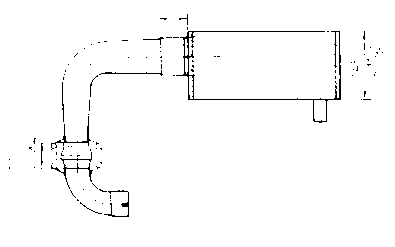
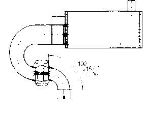
11Exhaust System
Detailed below are the three basic exhaust versions suitable for the 2702 engine. It is extremely important to
note the distance where the diffuser is inserted into the silencer. The distance of "I" is 10mm therefore the
diffuser MUST be inserted completely into the silencer then withdrawn 10mm.
1x 278 E19U Connection Bow
Ver. 1 1x 278 T19U Diffuser cone (straight) l = 10 mm
or Ver. 2 1x 278 T20U Elbow (90°) l = 10 mm
or Ver. 3 1x 278 T21U Elbow (180°) l = 10 mm
1x 278 E4U Silencer
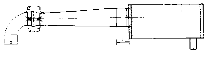
Version 1 (Straight Version):
Version 2 (90° Elbow Version):
Version 3 (180° ElbowVersion):
|
        http://www.ultralightnews.ca/ Page 28 of 31
The Ultralight News - your one stop shop!
Please note, the performance specified for this engine will not be obtained if an exhaust variant is used which
differs from the three basic versions. As a result from such modifications, it is possible that damage may
occur to the engine. There will be no liability by Gobler-Hirthmotoren KG to provide any warranty for any
malfunction or damage incurred by such modifications.
11.1Exhaust parts and measurements
278 E4U Silencer Complete
Weight : 3,2 kg
278 E19U Connection Elbow
Weight : 0,6 kg
278 T19U Diffuser Cone, Complete
Weight: 1,5 kg
278 T20U Elbow 90°, complete
Weight : 1,4 kg
268 A11U Clamp
54.1
Spring
278 T21U Bow 180°, complete
Weight : 1,4 kg
278 H4U Ball Joint
Weight : 0,26 kg
|
|
http://www.ultralightnews.ca/ Page 29 of 31
The Ultralight News - your one stop shop!
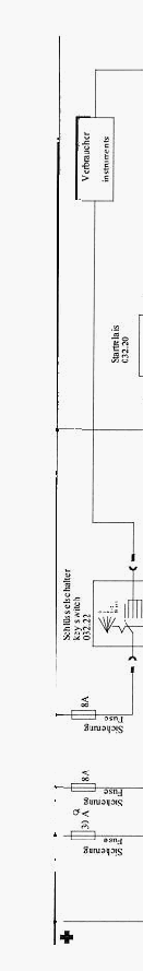
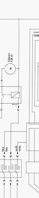
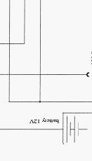
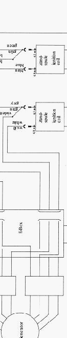
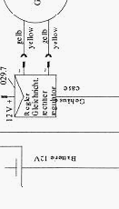
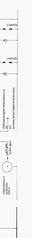
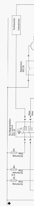
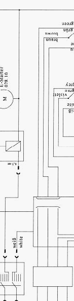
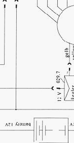
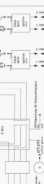
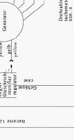
12Wiring Diagrams
The following two diagrams for the single- and dual-ignition systems show the PVL ignition system.
These wiring diagrams should be understood as suggestions for the periphery of the ignition system.
Cross section in general: 1.5mm²
Cross section from/to Electric Starter: 16 mm²
|
        |
      |