| UPAC member Norm Hull submitted a lengthy report for the UPAC News! The full report is available from Norm 613-267-1341 or
email norull@igs.net It is also on the Challenger Owners web site www.challenger.ca The thrust of his safety report was to determine 'WHY" the cog
belt on the reduction drive failed and to inform Challenger owners to
hopefully prevent a recurrence of an event that could very easily have
fatal consequences. Quad City Ultralights, manufacturer of the Challenger,
and National Ultralight, their Canadian distributor, both emphasize that a
cog belt failure is a very rare occurrence.
Challenger ultralight aircraft belt drive failure.
SYNOPSIS
The float equipped Challenger II was conducting a take-off from a small
lake into a 15 mph wind. Immediately after lift-off at full power (6300
rpm) the tachometer rpm began fluctuations of about two hundred rpm above
normal take-off rpm. The rpm increased momentarily and would then return
to slightly above normal take-off values. The fluctuations lasted about 2
seconds followed by a sudden and complete loss of thrust and an engine
over-speed in excess of 7000 rpm.
The aircraft was accelerating through about 42 mph in a shallow climb
attitude at a height of about 30 feet and in a high drag (take-off flap)
configuration when the thrust failed. The aircraft immediately entered the
stall regime and began to mush towards the lake surface at a steep angle
that resembled a helicopter auto-rotation. The pilot was able to control a
slight nose-up wings level mush attitude to impact just short of the
rugged shoreline.
Total airtime was less than10 seconds. Shoreline witnesses stated that
the aircraft appeared to descend very steeply then it disappeared in the
splash. One witness thought the aircraft had crashed and ran to contact
rescue authorities. The aircraft remained afloat and was towed back to its
base.
FACTUAL INFORMATION
- The aircraft, manufactured by Quad City Ultralight Aircraft Corp. (QCU),
was powered by a Rotax 503, two-cylinder, Dual Carb, Dual Ignition, two
stroke engine rated at 52 horsepower at 6600 rpm.
- The aircraft was fitted with the 60 inch propeller and HEGAR re-drive
using a Gates PowerGrip HTD� (High Torque Drive) 960-8M-50 belt.
-The HTD reduction drive belt was found completely devoid of all of its
*cogs.
-The reduction drive belt had been in service 2 years with a total of
83 hours logged on it.
-QCU recommends belt replacement after 100 hours or one year in
service.
-The belt tension and condition was inspected by the owner-pilot prior
to the flight and appeared to be "tight" and in pristine
condition.
- The aircraft underwent a 50-hour inspection by an AME 10 operating
hours prior to the event. The inspection included the condition, tension
and integrity of the belt.
-The aircraft was inspected after the event and no structural damage
was found.
-The Puddlejumper floats were examined after the event and no damage
was found.
-The belt tracking was found to be accurate.
-The drive sprocket did not exhibit evidence of excessive of wear.
-Except during flight, the failed belt had not been unduly exposed to
environmental elements. The aircraft was either hangared or an engine
cover was used.
-An expert examined the failed belt (less cogs) and opined that it did
not exhibit evidence of excessive wear, delamination or deterioration.
* Note: The PowerGrip System is described by the manufacturer as
providing positive slip-proof engagement by the belt teeth meshing
smoothly with the sprocket grooves. To better understand this report from
a Challenger user/maintainer�s perspective: The belt teeth are termed
"cogs" in accordance with common Challenger terminology. The
sprocket has protrusions which resemble teeth that extend between the
sprocket grooves.
These protrusions are termed "teeth" in this report. The
popular and incorrect belief is that these sprocket teeth drive the belt.
The positive engagement of the semi-circular belt cogs with semi-circular
grooves in the drive sprocket is what drives the belt. It is therefore
essential that the belt be tensioned to properly seat the belt cogs firmly
into the grooves. The sprocket "teeth" would be better described
as spacers between the sprocket grooves.
RESEARCH
It was found that a substantial amount of information is available on
the care and maintenance of the Rotax 503 aircraft engine. Specific
information on the Challenger reduction drive belt inspection, tolerances,
system components, serviceability, tensioning procedures, tension values
and belt care is sparse to non-existent.
When a drive belt fails the loss of thrust is instantaneous and
virtually without warning. Drive belt failure, unlike a number of engine
failures, provides no obvious warning of an impending failure except
through detection during knowledgeable pre-flight belt drive inspection.
Information on the care and handling of belts prior to installation was
also found to be sparse to non-existent.
Warnings not to mishandle (crimp) the belt are placed on one particular
equivalent brand of belt in 5 languages. There was no such warning o n the
failed belt. The normal fashion for a synchronous belt to fail is by loss
of cogs. Any other failure is abnormal. The shearing of belt cogs can be
caused by excessive shock loads applied to the belt. Belt performance is
generally unaffected in ambient temperature environments of -30F to
185F.
Belt cracking can occur under extreme low temperature startup. If a
belt is removed and reinstalled to run in the opposite direction
accelerated wear will result from a mismatch of the established wear
pattern. Synchronous belts are not date stamped and have a shelf life of 8
years without a reduction in performance.
One manufacturer�s policy is to not ship drive belts to suppliers
more than 5 years after belt manufacture. A mandatory or suggested belt
in-service life imposed by manufacturers was not found. Instructions
supplied with the re-drive state the belt should last 200 hours or more
but recommends replacement after 100 hours or 2 years in service.
During industrial application GT belts reportedly achieved a service
life of several thousand hours prior to routine replacement. GT2 belts
have not been on the market long enough to establish a service life
profile. Synchronous belts continue to evolve with material technology and
construction design. The first generation (1988) Gates PowerGrip HTD�
belt subsequently evolved into an improved PowerGrip GT� version.
The GT belt has a modified cog profile resulting in complete cog flank
contact that eliminated stress concentrations and cog deformation under
load. This greatly increased belt life and resistance to ratcheting. The
Gates PowerGrip GT2� version was introduced in February 2000. The GT2
belt features a longer and more robust life and with its redesigned deep
cog profile is capable of transmitting up to 200% more power than previous
PowerGrip GT and PowerGrip HTD belts.
When tested against competitor belts at sprocket speeds up to 9000 rpm
the GT2 belt outlasted the competitor belts more than two to one. As
patented belt designs expire numerous generic versions enter the
marketplace. There are presently at least 12 different brands of
synchronous belts on the market. A recently introduced belt features a
small lateral groove along the face of the cog.
The purpose of the groove is to allow the release of trapped air and to
reduce noise generation. QCU, the manufacturer of the Challenger
Ultralight was requested to provide the research data or to provide the
foundation for the imposition of their 100-hour, one-year in-use
limitation placed on the re-drive belt.
The stated belt limitations imposed b y QCU in the Challenger 50 Hour
Inspection Report was found to be arbitrary and without foundation. The
QCU imposed belt limitations remain unchanged despite technological
advances in belt design and durability.
The 880 8M 85 synchronous belt used on the Zenair 601 is about an inch
wider and 6 inches shorter than the 960 08M 50 belt used on the
Challenger. Belt life is projected to be a minimum of 500 hours of
operation utilizing a Subaru 100 hp 4-stroke engine at 4500rpm. While
utilizing pre-G2 belt technology and design, Zenair belt usage to 850
hours is commonplace in applications up to 200 horsepower.
There is no specific calendar limitation imposed on the belt. One
reported premature belt failure occurred with indications that the belt
was not tensioned or tracked correctly. Information on belt tensioning
procedures is apparently not provided with the re-drive system.
"V" belts depend on friction to transmit power. V-belt
applications such as that used on the Challenger cooling fan sustain
normal wear during service and become "loose". The common
perception that fan belts stretch with wear is only partially correct. The
belt shoulder is compressed, burnished and worn during use causing the
belt to become thinner and hence "looser" on the pulley.
If the Challenger pulley is not compressed through shim removal the
belt will eventually slip in the pulley while under load. A Challenger fan
belt with 150 hours logged in service was examined and found to be
virtually the same length as the new replacement however the used belt was
2 mm narrower at the shoulder.
Synchronous belts function under a different principle than V-belts.
The synchronous belt itself may wear and stretch only minimally. It is
absolutely essential that the prescribed pre-tension value be maintained
as well as the system drive sprocket integrity and sprocket alignment
(tracking).
The pitch of the belt is the distance between the center of each cog
measured on the pitch line (circular pitch). The Challenger belts have an
8mm circular pitch. If the belt stretches with age and use there is a
corresponding belt pitch change. The pitch change allows a mismatch to be
generated between the face of the sprocket groove and the driven side of
the belt cogs. The mismatch creates increased friction between the two
surfaces thus accelerating cog wear and sprocket wear.
Evidence of this wear manifests itself at the driven shoulder of the
belt cogs and at the shoulder of the drive sprocket groove. In extreme
cases, evidence of belt facing material may be exhibited on the drive
shoulder of the sprocket grooves. Over-tensioning the belt can impose
higher than design bearing and shaft loads and leads to reduced belt and
bearing life. When the belt is severely under-tensioned an inherent
self-tensioning characteristic is generated by belt circumferential force
against the sprocket grooves.
Since the groove face is inclined, the belt slides up the groove while
under load which in turn increases overall belt tension. The increased
tension leads to increased stress on the cogs, accelerated cog wear and
reduced belt l ife. The sprocket groove and cog combination will take the
path of least resistance and the cogs will ride high on the sprocket
grooves and teeth or even ratchet by them while under high torque load
such as during take-off.
In due course the drive sprocket will either damage or shave off belt
cogs in just a few revolutions of the belt. Ideal belt tension is the
lowest amount that properly seats the belt in the sprocket grooves during
maximum loading at all points around the drive.
One method for measuring the ideal tension employs a sonic measuring
device the size of a cell phone. This device operates on the transverse
vibration of strings theory which holds that a belt, when strummed like a
guitar string, vibrates at a specific natural frequency based on its
tension, mass and span length.
During research into this event the formula to calculate belt drive
pre-tension values was entered into a computer using the manufacturer�s
engineering software. The engineering formula was entered into the
computer using the application data of a Gates Powergrip 960-8M-GT-50 belt
driving an industrial ventilator propeller powered by a Challenger engine
using re-drive parameters. (Gates does not endorse application of its
product on aircraft).
Using a 30 tooth, 3.01 in. DriveR sprocket and a stock 80 too th, 8.02
in. DriveN sprocket (the Challenger uses a 78 groove DriveN) with a 10
inch center distance the computed slack side belt deflection was 0.150
inches (about 5/32in.) with an applied belt deflection force of between
27.52 and 29.39 pounds for a new belt and 23.78 to 25.65 pounds for a
"used" belt.
The computed sinusoidal wave frequency, or Sonic Tension Value, for a
properly tensioned used (Challenger) GT belt is between 156 and 163 Hertz.
Also determined was a handy rule-of-thumb tensioning method which could be
used by Challenger owners: The belt, at mid-span, should deflect 1/64ths
of an inch for each inch of belt span at about 28 pounds force for a new
belt and 24 pounds for a used belt. The Challenger belt span is about
10.25 inches which amounts to about 3/16ths of an inch cold belt
deflection measured on the slack (exhaust side) span.
Synchronous belts cannot be run at unlimited speeds and power. The
limitation of a synchronous belt drive system is the sprocket "Rim
Speed" which is almost identical to the belt speed. This speed
limitation is 6500 feet per minute (fpm) which is much greater than speeds
the Challenger 7075-T6 aluminum drive sprocket attains at full
power.
Above 6500 fpm speeds standard cast iron sprockets can develop cracks
and fracture. The actual "belt" limitation of a drive system
relates to the tension imposed on the belt by the drive horsepower. The
PowerGrip GT2 belt carries a rating of over 120hp at a 6500fpm Rim Speed.
A random Challenger take-off engine RPM of 6300 was selected and entered
into the computer using a 30 groove drive sprocket and a custom 78 groove
DriveN sprocket.
The following was determined:
Rim Speed 4927 fpm with a prop Speed of 2423 rpm and a 633lb. belt pull
(Belt Shaft Load). At a take-off RPM of 6500 the Rim Speed is 5084 fpm and
a prop speed of 2500 rpm is attained. A new GT belt was installed on the
incident aircraft and pre-tensioned to 3/16in.
The belt felt much tighter than the owner-pilot was accustomed to
during his previous pre-flight belt inspections. Because the belt felt
"too tight" for bearing li fe, the rule-of-thumb deflection was
increased an additional 1/16in. to 1/4in. The maximum engine rpm attained
after installation of the new belt was about 200 rpm more than the average
maximum attained prior to the belt failure.
ANALYSISThe tachometer rpm fluctuations observed by the pilot during lift-off
were caused by ratcheting and/or the initial failure of the first belt cog
or cogs. Each revolution of the belt transported the cog-damaged sector
toward and past the lower engine sprocket drive.
 The
engine momentarily increased rpm due to lack of shaft resistance until
cogs were again in contact with the sprocket drive grooves/teeth. The
tachometer rpm indication momentarily increased and decreased each time
the cog damaged or cog-free sector of the belt was transported past the
sprocket drive. With each revolution of the belt, the cog-damaged sector
was enlarged by the over-speeding sprocket drive that damaged or shaved
off more cogs. Finally the damaged sector was large enough to allow the
engine sprocket drive speed to exceed 7000 rpm. The
engine momentarily increased rpm due to lack of shaft resistance until
cogs were again in contact with the sprocket drive grooves/teeth. The
tachometer rpm indication momentarily increased and decreased each time
the cog damaged or cog-free sector of the belt was transported past the
sprocket drive. With each revolution of the belt, the cog-damaged sector
was enlarged by the over-speeding sprocket drive that damaged or shaved
off more cogs. Finally the damaged sector was large enough to allow the
engine sprocket drive speed to exceed 7000 rpm.
All the remaining cogs were instantly shaved off when they were
transported to the high-speed sprocket drive; akin to the action of a wood
router. It was at this time that all thrust was lost. From start to finish
the process took less than 3 seconds. The increase in maximum engine rpm
attained following installation of the new belt was evidence of the
previous belt�s mismatch between the cogs and the drive sprocket grooves
due to belt pitch change.
The mismatch created additional friction that absorbed engine torque.
The float-equipped aircraft was at low altitude, in a shallow nose-up
attitude, in high drag configuration just above the stall speed when
thrust was lost. (The dead man�s curve). The aircraft rapidly
decelerated into the stall regime. Insufficient height existed to lower
the nose to effect a classic stall recovery.
Fortunately, the Challenger�s stall characteristics allowed the
aircraft to mush with substantial elevator and flaperon authority. As a
consequence, the pilot had adequate lateral and pitch control throughout
the steep descent until splashdown.
Had the Challenger possessed classic aircraft stall characteristics the
nose would likely have dropped during the stall and in all probability the
tip or tips of the floats would have dug in at impact causing the aircraft
to flip inverted.
FINDINGS
1) The engine driven reduction belt failed under high torque at a
critical moment during take-off.
2) The lower than optimum engine rpm prior to the occurrence was
evidence of excessive belt friction.
3) The belt failure was caused by inadequate tensioning of the belt.
4) The failed PowerGrip HTD belt was an earlier, less robust version of
current PowerGrip GT belts.
5) Synchronous belt manufacturers� prescribed belt-tensioning values
and procedures are not readily available to aircraft owners, pilots and
maintainers.
6) The pilot was unaware that minor tachometer rpm fluctuations to
above normal values at take-off power indicated imminent belt failure and
total loss of thrust.
7) The one-year, one hundred hour service life imposed by QCU on the
Challenger synchronous belt is arbitrary and without foundation.
8) For liability considerations the Gates PowerGrip belt application on
the Challenger (and other) aircraft is not endorsed by Gates Rubber
Company.
9) Direction of rotation should be identified on the belt and that
direction should be maintained for the life of the belt.
10) The Challenger aircraft�s docile stall characteristics averted a
potentially serious accident.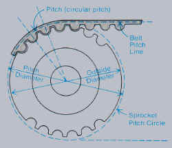
Flight Safety Suggestions for Challenger Owners, Pilots and
Maintainers.
-Discard any old drive belt or those marked "PowerGrip HTD"
regardless of the belt�s service life.
-Preflight, examine the re-drive belt tension to ensure it does not
exceed �" deflection. (Apply tension pressure with your thumb till
it hurts, you then have about 25 pounds pressure).
- When measuring the belt deflection pull the propeller backward
against engine compression to slacken the belt�s slack side.
-Preflight, rotate the propeller and examine all 120 belt
"cogs" for excessive wear or damage.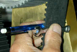
-Preflight, tap or pluck the belt, if it doesn�t vibrate its probably
too loose.
-Periodically examine the belt�s neoprene backing for hairline
lateral cracking. Cracking is detected most easily where the belt backing
is stretched around the lower drive sprocket. Alternatively, examine it
around the upper sprocket.
-If any belt damage, excessive wear or cracking is found replace the
belt immediately.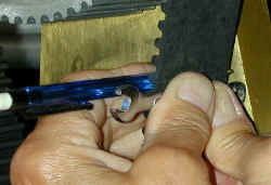
-Always use smooth throttle handling to reduce the risk of shock load
failure.
-If practical, protect the belt from moisture, chemical contaminants
and direct sunlight. With proper care and maintenance the GT belt should
provide at least 5 years and 500 hours of Challenger service. The GT2 belt
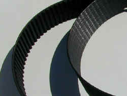
should provide at least 5 years and 700 hours of service. Four JPG
photographs are attached showing, for comparison, a new belt and the
failed belt, belt/sprocket specifications and a suggested belt tensioning
procedure.
Picture summmary
A. New and failed belt.
B. Belt pitch length is measured along the belt pitch line.
C. Preparation to measure belt deflection.
D. Prevent belt twist and apply pressure.
(Note about � inch deflection. )
Editors Note.
The author spent 23 years as a professional Aviation Safety Investigator
(Canadian Aviation Safety Board) and Aviation Safety Consultant (Accident
Investigation & Research Inc.) His professional responsibility during
this period was to identify aviation safety deficiencies. Determining
"WHY" the event happened or "WHY" a component or
system failed is part of that process.
The thrust of this Challenger flight safety report was to determine
"WHY" the belt failed and to educate Challenger users about the
synchronous belt application on their aircraft. Dissemination of this
report to Challenger users will hopefully prevent a recurrence of an event
that had potentially disastrous consequences. A draft copy of this report
was distributed to the owners of National Ultralight Inc., the exclusive
Canadian Distributor of the Challenger. They declined to comment.
Also check out what can happen
when drive belt fails!
|