Challenger
Upright Motor Mount
Ultralight aviation has jumped ahead in leaps and bounds since 1978 when it first took
form. We started by hanging our butts out from under a set of Easy Riser, wings powered by
Mac 101 chain saw engines. Then came the Eipper weight shifts powered by single
cylinder Yamaha go cart engines. We then moved up to the Canadian built weight shift Atlas
with a little Rotax 299 cc engine. At the same time Eipper introduced the new Quick E, a
weight shift rocket powered by a 430 Cuyuna with 35 HP.
Next came the revolutionary Quicksilver MX. Now for the first time you had a plane with
a seat and a control system. Mind you it was only two axis control and you were still
sitting out in the wind, with a top speed of 35 m.p.h., and still flying on those
"damned wires."
Not to be outdone a Canadian company hit the scene with the Lazair. Finally a true
three axis ultralight, with two engines - for reliability - right? A little like having
two wives! Mind you some folks weren't happy with only two, and installed a third, then a
forth! But alas you still only had a 35 m.p.h. cruise, were still stuck out in the wind,
and when it was windy the plane was to LIGHT to fly!
So what next? In 1984 Quad City introduced the Challenger. This aircraft was like going
from a prop engine to a jet engine. You had true three axis control, power was up to 50
ponies, and cruise speed nearly doubled to 65 m.p.h.! To top it all off the plane could be
built in under 100 hours when covered in dacron sail cloth. This was truly the start of
the "next generation."
I was introduced to the "next generation" at Sun N Fun in Lakeland Florida.
Dave Goulet was kind enough to take me up for a demo flight, and on landing I gave him a
deposit on a two place Challenger.
Two months later a Challenger kit was on my trailer and I was on my way back to Canada.
A month later the first Challenger imported into Canada was up an flying! Two weeks later
Challenger 1 had 40 hours on it in a training environment. With a student on board at
about 2,000 feet, and the plane cruising along at 55 m.p.h., at 6,000 rpm the engine
backfired twice and quit.
One of the good things about a Challenge is that it does glide quite well! With 2,000
feet of altitude we had about 15 minutes to find a spot to land. Unfortunately for us it
had rain quite heavily for the past 3 days and most of the sod fields around us were soft.
Realizing this we set up to land into the wind, at about 75 feet I drop the nose to pick
up some airspeed, then leveled off at about 5 feet. With the extra speed we floated, and
floated and floated until finally we had to touch down. The mains touched first. using the
stick we were able to keep the nosewheel up until the last second. It touched traveled
about 10 feet dug into the soft ground and snapped off right below the bearing yoke.
The
nosewheel then came up through the lower fuselage fabric. At the same time the nose of the
plane went forward and into the ground bending the lower formers as it hit. In a flight
training environment especially during the summer you can't afford to be down time.
Another good thing about the Challenger is that it is relatively easy to repair. In fact
two days later the nosewheel was replaced using a chromoly steel shaft with the steering
yoke welded to it, instead of the aluminum tube with the steering yoke RIVETED to it (it
snapped off right at the rivet holes) the airframe was fixed, and the fuselage recovered.
Tearing the engine down to find out what had happened was the next job. Upon
disassembly the engine was in perfect shape! Except for the two end crankshaft bearings.
Both bearings had failed. The plastic liner which supports the balls in the bearing had
MELTED. With only 40 hours on the engine, the feeling was that the bearings must have been
defective.
Three new bearings, one on the magneto end and two on the PTO end were
installed and the 503 was cleaned, resealed and reassembled. Four days after the failure
the plane was up and flying again! Three weeks and 68 hours later, she was back in with
the same engine problem. This time no damage to the plane. Disassembly of the engine
revealed that the same two bearings had failed again!
A call to the Rotax distributor revealed the problem. The Challenger uses a belt drive
system. Heat, vibration, tension, and a harmonic resonance from the use of the this system
were destroying the bearings. Suggested solution - switch to a Rotax gear box.
Simple right? A call to the Quad City revealed that they had no plans to switch to from
belts to the Rotax gear drive, and didn't recommend it. Thus if anyone was to do it they
were on their own.
Looking around the industry revealed that most of the other leading manufacturers were
NOW using the Rotax gear drive. Some like Maxair had even taken their engines which were
formally mounted upside down, and mounted them upright. With nearly 300 hours of trouble
free flying on an upright mounted 447 Rotax gear drive equipped Buccaneer Amphibian, the
decision was made that changing to an upright motor mount on the Challenger was worth the
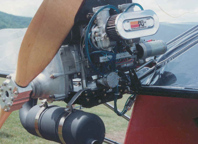
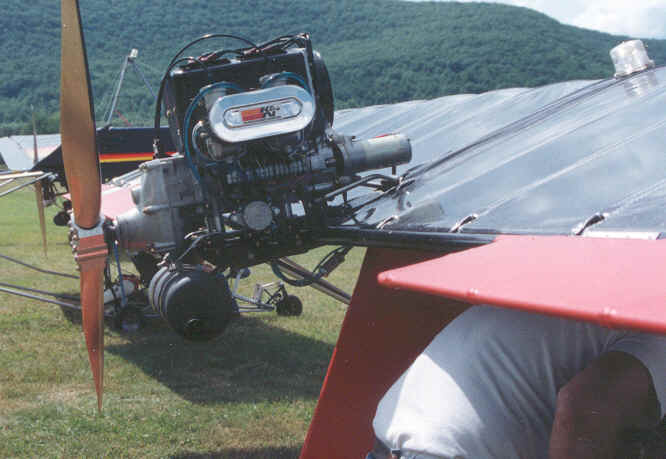
gamble. How to do it quickly, economically, and safely! Challenger Upright Motor Mount
First problem
What ratio to use when ordering the drive. The Challenger back then had a 2 to 1 ratio.
This spun a small prop very fast - very noisy and inefficient. It also sets up a harmonic
vibration through the engine and airframe at cruise RPM. The Rotax distributor suggested
a 2.58 to 1 reduction cost at that time about $350 bucks CDN.
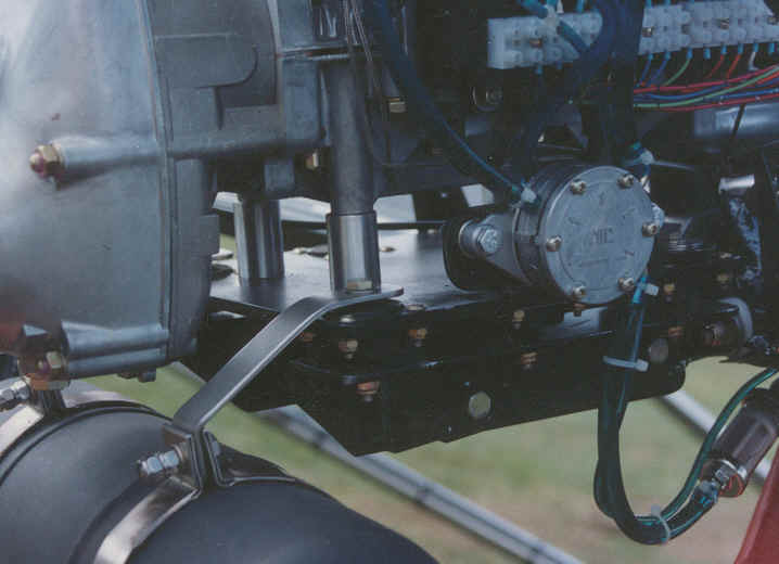
Problem two - motor mount.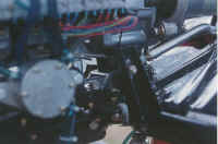
Since the Challenger comes with a flat motor mount plate using 6 Lord mounts, which is
what the Buccaneer uses I decided to stick with the same base plate, and motor mounts.
After all if the plate and mounts are the same and the Challenger is mounted upside down
and the Buccaneer upright, and no problems were evident in either for the time that they
had been used, just over 100 hours for the Challenger nearly 300 for the Buc then it
seemed logical that the mount didn't care whether it had an engine suspended from it or
supported by it.
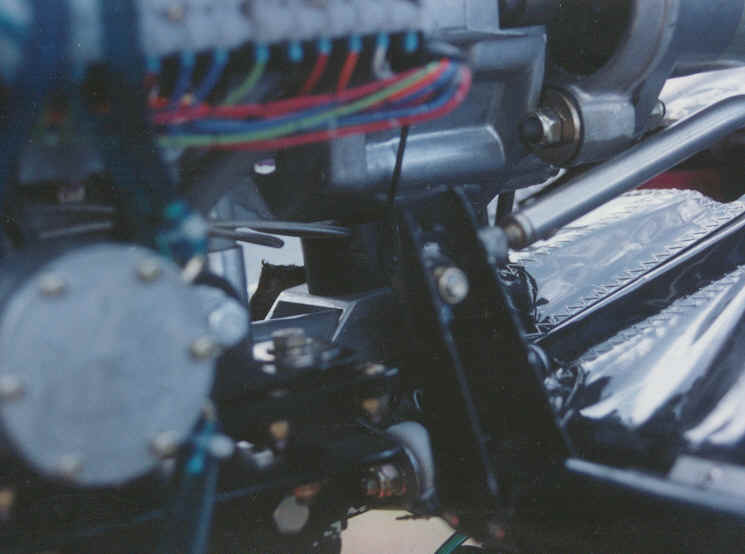
Problem three
How to bolt it onto the root tube? The Challenger uses a set of 90 degree aluminum angle
plates with spacers to support the motor mount plate. Since the motor was going to be
upright the plates couldn't be used. Or could they? By taking and reversing the plates
side to side. The angle that was used on the left side facing down is now placed on the
right side facing up, and vice versa for the right. But what about the engine angle? Good
question! Use the same angle. Level the plane so it is sitting on all three wheels.
Install the motor mount the way if comes from the Challenger factory. Use an angle gauge
and measure the angle. Now reinstall the mount upright using the above
technic. Don't
redrill your root tube to get this angle. Redrill the REAR and only the REAR hole in the
two 90 degree aluminum angle brackets. You can still use the two aluminum spacers that go
between the root tube and the angles since the holes haven't changed.
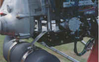
Problem 4
The aileron horns now hit on the side of the motor mount. Fixing this problem will require
a little bit of precision. To fix this problem it is necessary, (not in all cases) move
the aileron horns outboard 1 inch. This might require moving the aileron hinge as well
depending on where you installed it. Draw a line down the center of your aileron torque
tube, across your horn. Remove the horn. Cut the aileron torque tube. Using the line you
drew reposition and rerivet the horn. Repeat for the other side.
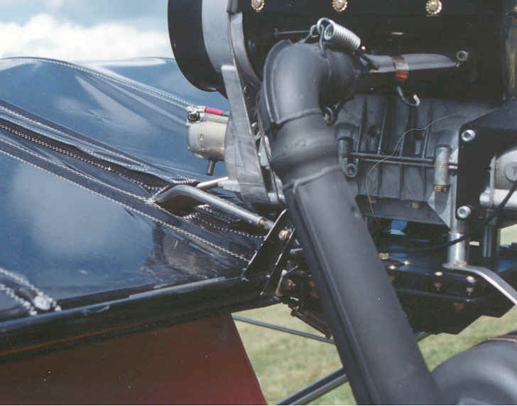
Problem 5
The recoil hits on the root tube when the motor rocks forward. To solve this problem we
are going to raise the motor 1 inch. Take a 1 inch piece of thick walled aluminum tube.
Using a pipe cutter cut 4 pieces of tube 1 inch long. Use a file to debur and smooth the
ends. Make sure all of the pieces are EXACTLY the same length. Remove the 4 studs from the
bottom of the engine that were used to hold the engine onto the motor mount plate. Since
we are going to raise the engine these will not be long enough. Pick up 4 new studs or 4
bolts that are long enough to go the correct length into the engine, and through the plate
without bottoming out. Make sure that you remember to measure for a flat washer and
lockwasher. To help position the bolts better in the aluminum spacers take 4 pieces of
rubber tube slice them down the middle and install them into the spacers. Now install a
lockwasher and flat washer onto one of the bolts. Feed it thru the motor mount plate.
Place an aluminum spacer with the sliced rubber tube over the bolt and screw the bolt into
the bottom of the engine. DO NOT tighten all the way up. Repeat for the other bolts. NOW
snug and torque the bolts. |