|
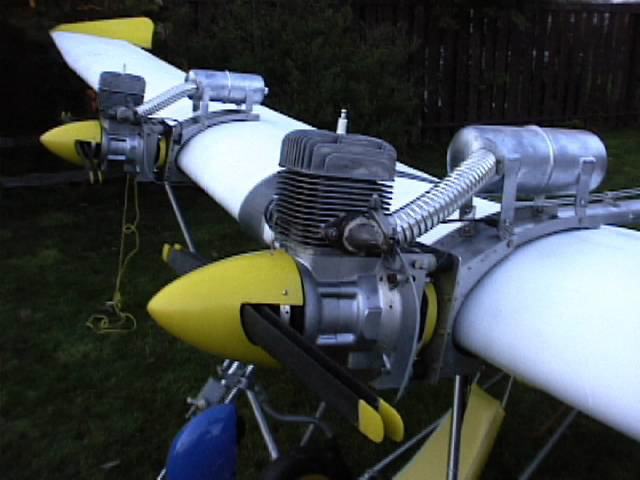
Technical Information
Horsepower: 9
Carburetor: Tillotson, diaphragm with internal pump and filter
Ignition system: Bosch magneto,
Spark plug: Bosch M4-AC 18mm or Champion K-7 18mm
Oil mixture: 1:40 leaded fuels, 1:32 unleaded fuels
Spark plug gap: .016 - .020
Point gap: .014 - .018
Ignition timing: .138 - .158 B.T.D.C.
Ignition timing :.147
Mag air gap: .010 - .013"
Crank end play: .001 - .009
Cylinder bore: 2.441
Torque values
Spark plug 360 inch lbs.
Cylinder head nuts 200 - 220 inch lbs. retorque every 100 hrs.
Flywheel hub 390 - 400 inch lbs.
Crankcase screws 100 - 110 inch lbs.
Removal - Engine from airframe
To remove the 185 cc Rotax ultralight engine from the airframe it may be necessary to: If
aircraft is equipped with a battery disconnect the battery ground cable before starting
any work!
Disconnect:
-Fuel lines at carburetor
-Throttle linkage
-Choke linkage
-Ignition Wiring
-Exhaust system
-Remove props, and store in safe place.
To remove engine
Carefully remove 4 nuts holding recoil to motor mount, pull engine forward and free of
mount.
Caution: engines are heavy and awkward to handle, make sure adequate
help is available.
Disassembly - Magneto removal
Tools required
Bombardier puller part #
() mm socket
10 mm socket
ratchet
Vice
Air or electric impact
Magneto Removal
To remove the magneto first remove the 3 10mm nuts retaining the recoil cup. Remove the
cup. Place the engine assembly into a vice, clamping down onto the lower crankcase
castings.
With the engine secured, and while locking the crankshaft to prevent it from turning, use
an electric or air impact and a () mm socket to remove the flywheel nut, and lock washer.
With the nut and washer removed, install the Rotax puller, make sure that the puller is
threaded on as far as possible onto the magneto. Snug up the puller bolt, again secure the
crankshaft, and using an air or electric impact and an () mm socket turn the puller bolt
clockwise, the magneto should come free.
Once free gently pull out on the magneto, and remove it from the engine.
Inspection:
-Inspect the magneto for signs of wear or damage.
-Inspect the crankshaft key way for signs of damage.
-Inspect the crankshaft threads for signs of damage.
Cylinder head removal
Tools required
13 mm socket
ratchet
Cylinder head removal
To remove the cylinder heads, disconnect the spark plug wire, and remove the spark plug,
remove the 4 nuts and flat washers located inside the cylinder head.
The cylinder head will now lift off.
Inspection:
-Inspect the interior dome of the cylinder head for signs of damage.
-Inspect the head gasket for signs of leakage
-Inspect the cylinder head spark plug threads for signs of damage
-Inspect the spark plug for colour of burn.
-Inspect top of piston for carbon build up.
Cylinder removal
Tools required
Hands, fingers
Rubber mallet
Cylinder removal
To remove the cylinder, grasp the top of the cylinder with your hand and gently lift up.
It may be necessary to gently tap the cylinder at the base, with a rubber mallet to break
it free from the cylinder base gasket.
Caution: When removing the cylinder be careful that the piston and rod assembly are not
allowed to bang against the side of the crankcase or cylinder retaining bolts.
Inspection:
-Inspect the interior of the cylinder for signs of wear.
-Inspect the interior of the cylinder for signs of seizure.
-Inspect the decompressor for signs of seizure of leakage.
-Inspect the exhaust port for signs of carbon build up.
-Inspect the exhaust studs for signs of tightness.
-Inspect the carburetor mounting bolts for signs of cracking.
-Inspect the carburetor mounting bolts for tightness.
Piston removal, pin and bearing removal
Tools required
-Ice pick or other pointed tool
-Rags
-Eye protection
Piston, pin and bearing removal
To remove the piston place the remaining engine assembly on your bench, in such a way as
to give you easy access to the piston pin retaining clip.
With an ice pick or other sharp tool, insert it carefully into the cut out in the piston,
so that it fits underneath the circlip.
With eye protection on, and a rag in the other hand to prevent the clip from flying free.
Pry out on the clip.
With the clip removed, insert a socket into the other side of the wrist pin hole and tap
the pin out. Once the pin is free of the connecting rod, the piston and pin can be lifted
free. Remove the wrist pin bearing from the connecting rod end.
Inspection:
-Inspect the piston for
signs of damage.
-Inspect the piston for signs of seizure.
-Inspect the rings for signs of seizure.
-Inspect the ring lands for signs of damage.
-Inspect the ring dowels for signs of damage.
-Inspect the bottom of the piston for a shiny ring, a sign of wear.
-Inspect the wrist pin for wear.
-Inspect the wrist pin for signs of bluing or heat.
-Inspect the wrist pin for signs of damage, or pitting.
-Inspect the wrist pin bearing for signs of wear.
-Inspect the wrist pin bearing for signs of foreign material.
-Inspect the wrist pin clip retaining groove for signs of wear.
Splitting
the crankcase
Stator unit removal
Tools required
Flat screw driver
Hammer
Chisel
Procedure
Before removing the stator plate take a hammer and chisel and indent a
mark in the stator plate and crankcase half. This will aid in timing the
engine during reassembly.
To remove the stator unit remove the screws holding the stator to the
lower crankcase. Remove the spark plug wire cap from the coil wire.
Remove the ignition shut off wire from its connector. Remove the
generating wire from its connector if connected.
Gently pull the stator unit towards you while pulling the coil wire
through the rubber grommet. Remove the stator unit.
Inspection:
-Inspect the points for wear or damage
-Inspect the condensers for signs of oil around the sealing surfaces
-Inspect the coil for signs of damage.
-Inspect wiring for signs of pinching or cutting. Disassembly -
Crankshaft removal
Tools required
Propane torch
Screw driver
Plastic/rubber hammer
Procedure
To split the crankcase it is first necessary to remove the 5 screws
holding the case together. These are located on the magneto side of the
crankcase, directly behind the stator plate.
Note : 2 of the screws are longer.
Once the screws have been removed, place the remaining unit in a vice,
clamping to the lower crankcase at the thick castings on the PTO side of
the crankcase.
With a propane torch, apply heat to the area of the lower crankcase on
the magneto side, around the bearing area. The purpose of this is to
expand the aluminum around the bearing retaining area, and make removal
of the crankcase from the crankshaft easier. Once heat has been applied
around the outer bearing area, using plastic hammer hit the crankcase in
the area of the outer housing. First one side of the case then the
other. The case should come free from the bearing.
To separate the case from the bearing on the other side, support the
case on a level wooden surface, again apply heat to the bearing area.
Place the nut used to retain the prop hub onto the shaft and screw it
down until it is flush with the top of the crankshaft. Then using a
rubber mallet or plastic hammer, while holding onto the lower end of the
crankshaft hit the end of the crankshaft. The crankshaft and bearing
should come free of the casing.
Inspection:
-Inspect seals for signs of leakage.
-Inspect bearings for signs of wear.
-Inspect crankshaft for signs of wear or damage.
-Inspect crankcase for signs of wear or damage.
-Inspect centre crankcase sealing area for signs of damage.
Inspection/Cleaning
-Inspect cylinder head dome for signs of damage.
-Inspect cylinder head for warpage.
-Inspect cylinder head spark plug threads for signs of damage.
-Inspect cylinder decompressor for signs of leakage.
-Inspect head gasket for signs of leakage.
-Inspect cylinder for signs of seizure.
-Inspect cylinder for signs of damage.
-Inspect wrist pin for signs of damage or overheating.
-Inspect wrist pin bearing for signs of damage.
-Inspect piston dome for signs of damage.
-Inspect piston skirt for signs of damage or wear.
-Inspect wrist pin clip seating area for signs of damage.
-Inspect under dome of piston for carbon build up.
-Inspect ring land seating area for signs of damage.
-Inspect ring land retaining dowels for signs of damage or wear.
-Inspect rings for signs of damage, wear or seizure.
-Inspect cylinder base gasket for signs of leakage.
-Inspect exhaust gasket for signs of leakage.
-Inspect intake gasket for signs of leakage.
-Inspect stator unit for signs of damage or wear.
-Inspect points for signs of damage or wear.
-Inspect wiring for signs of damage or pinching.
-Inspect condenser for signs of oil contamination, or damage.
-Inspect crankcase halves for signs of wear or damage.
-Inspect crankshaft for signs of wear or damage.
-Inspect recoil, rope, and mechanism.
Cleaning:
Tools required
Varsol or other good quality cleaner.
Wire brush.
Scraper.
Cylinder hone.
Murata acid.
Small brush.
Cleaning cylinder head.
Using a wire brush and good quality cleaner scrub the interior dome of
the cylinder head to remove carbon build up. If head gasket is stuck to
head remove it.
Cleaning cylinders
If cylinders have aluminum deposits remove using small brush and Murata
acid. Apply small quantity of acid wait a few minutes, flush cylinder
with cleaning solvent.
Hone cylinder with, when complete cylinder wall should have a noticeable
cross hatch pattern in the walls. Using wire brush, and solvent clean
exhaust port.
If cylinder base gasket is stuck to cylinder base remove it.
Cleaning piston
With the rings removed from the piston, use the wire brush/scrapper and
solvent to clean top of piston dome. Using old ring clean ring seating
area of carbon. Using pointed object, or screw driver ensure that no
loose carbon is attached to the underside of the dome of the piston.
Cleaning crankcase halves
Using paint brush and solvent remove any remaining dirt or oil from
crankcase halves. If center sealing gasket is still attached remove it. attached remove it.
Click here for parts for the
185 cc Rotax Engines
|
|
Ultralight Aircraft News Web Magazine Covering the World of Ultralight Aviation .
You may link to these pages or print
them out for your own personal use, but no part of this
publication may be copied or distributed, transmitted, transcribed,
stored in a retrieval system, or translated into any human or computer
language, in any form or by any means, electronic, mechanical,
manual, or otherwise, without the written permission of Ultralight News.
By copying or paraphrasing the intellectual
property on this site, you're automatically signing a binding contract
and agreeing to be billed $10,000 payable immediately. Copyright Ultralight News
|