|
The
recommendations in these updates must be
acted upon before they can be or any benefit.
For your own safety as well as the safety or those around you,
please take the time to make the recommended changes to your aircraft.
In the past six weeks we have had three engines sent
to us for service. Not one or them had the propeller bolts installed as recommended
in update S, item 5.4. Please
read these updates carefully and make the recommended inspections
and/or changes which
apply to your Lazair.
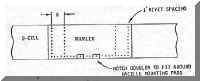
6.1
D-CELL SPLICE
As
you are probably aware, the D-cell skin is comprised of two sections - a
main skin and a tip skin. During
final inspection
of a batch of D-cells
recently. We discovered one which did not have sufficient overlap at the
junction of the main skin and the tip skin to allow the proper edge
distance for the rivets. Although
it is unlikely that
any D-cells were shipped with this defect, please check yours as
described below. Since the outboard end of the main skin is covered by the tip
skin, if the problem does exist, it will
not be obvious and must be checked carefully.
To
check the edge distance for the rivets, it is necessary to know the
position of the outboard edge of the
main skin.
To locate this edge, look at the trailing edge or the bottom or
the D-cell. By looking
inside, you should be able to see the outboard edge or the main skin.
Put a mark on the outside of the
tip skin
at this point and measure the
distance from this mark
to the inboard edge of the main skin (so you know the exact length of
the main skin). Then
transfer this measurement to the leading edge of the D-Cell. You
can now draw a
line on
the tip skin showing
the exact location of the edge of the main skin.
To achieve the correct edge distance, the rivets should be
located so that the centre of the rivet hole is at
least I/4
of an inch from the
edge of the skin. If
necessary, install additional rivets (with the required edge distance)
between the existing rivets.
If
the overlap on your D-cell is insufficient to permit the required
edge distance,
please contact
your dealer or
the factory and w e will make up a special splicing kit for your
D-cell(s) and ship it to you. e will make up a special splicing kit for your
D-cell(s) and ship it to you.
6.2
KEEP YOUR ASI COOL
Although
the Hall brothers airspeed indicators are surviving quite well on
the aircraft,
we have had
two reports of ASI's
becoming so hot that they actually bent slightly and were no longer
useable after being left in the rear window of a car.
6.
CARBURETOR NUTS
In Update 5.8 we reported on a
potential problem of carburetors working loose
and suggested that the nuts be
checked and
retightened periodically.
Since then
we have
determined that the
self-locking nuts work properly. but the studs work loose in the
crankcase. To prevent this from happening, we are now
lock wiring the nuts and
studs after installation of the carburetors at the factory. and it
is recommended that this be done on all Rotax engines.
To install the lockwire. Make sure the nuts are tight. then
drill a
small hole through
each nut (and the end
or the stud). Feed a single
piece or lockwire through both nuts and twist the ends together.
6.4
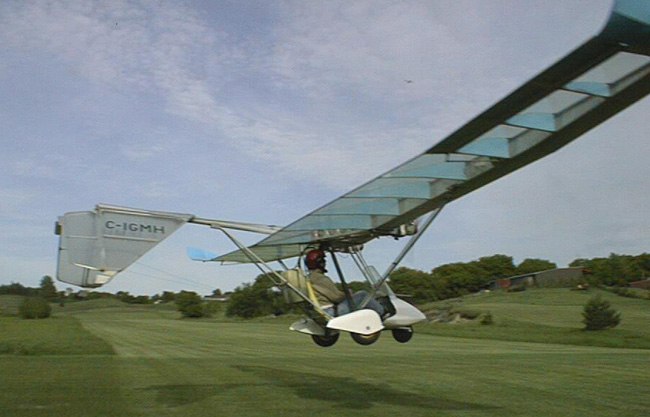
LARGER FUEL TANK INSTALLATION
Although as stated earlier. we do not
supply a conversion kit for the new 20 Litre (5 U.S.
Gal.) fuel
tank. many owners have
installed the larger tank and now that the new FAA rule specifically
allows a 5 gallon tank. many core owners may wish to make the conversion.
As stated previously. these changes
are not
recommended unless you
have had experience and have access to the equipment required for bending
thin wall aluminum alloy tubing. However.
for anyone who is qualified to do the job. the following guidelines are
provided:
1. To
achieve the proper centre-of-gravity. it is necessary
to move both the fuel
tank and the pilot forward. This
involves rebending and repositioning the seat tube (T44) as shown (or
replacing the T44
with the new T60 seat tube).
2. Make
a saddle for the new tank so that the weight
is carried by the T22's
at the
rear and by
the seat tube at the front. Do
not attempt to support the weight of 5 gallons of gasoline (about
140 pounds at 4 g's) entirely by the T22's.
6.5 RIVETS
IN P3 PLUGS
Although calculations and
testing have shown that one rivet would be sufficient to hold the P3 plugs
into the control
pushrods. we use two
rivets in each to provide a safety factor in the order of ten-to-one for
normal control surface loading. However.
it may be possible in the event of a mishap
(such as
an aircraft being
blown over
by severe
winds while tied down)
to apply stresses beyond the strength of the rivets and shear them off.
If your aircraft is ever involved in any type of incident which
could put abnormal loading on the control
pushrods they
should be inspected very carefully before the next flight. Pushrods
should also be inspected very carefully if you buy a used aircraft -
especially if it has been damaged. if
there is
any indication that a pushrod could have been overstressed. install
an extra rivet in the P3's for security.
6.6
PROTECT YOUR TAPE
All new Lazair's and many older
ones are now being covered in Tedlar.
while the operating life or the
Tedlar is expected to
be many times that
or Mylar
the life or the
adhesives used and the tapes has not been precisely determined.
To obtain the maximum life from
the tapes,
it is
recommended that
all tape
be protected from ultraviolet exposure.
This can be done in several ways.
If you intend to paint your Tedlar then the paint will afford some
ultraviolet protection but the degree of that protection will
depend on the
particular type of pigment
used in the paint. Aluminum
paint works best and it is therefore recommended that the tapes be painted
over with aluminum paint (regardless of whether or not
the balance
of the Tedlar is
painted). As
an alternative, the tapes holding the Tedlar in place may be
covered by a metalized tape (such as type 85O PAU. available from your
local 3M distributor). In
addition to providing ultraviolet protection,
this tape creates a very neat, clean appearance. especially when used over
the foam tape on the ribs.
6.7
ROTAX ENGINES ON .016 INCH D-CELLS
In Update 5, item 5.7 we stated
that the use of Rotax engines on Lazair's with .016 inch
leading edge skins was not recommended.
This statement
was not based on any particular experience, but rather on a lack of
experience. At that time, we
had one demonstrator flying
with this combination,
but we did not
have sufficient time
on it to evaluate the results. Since
then, our demonstrator has continued to perform well. however, one dealer
"who installed Rotax engines on
.016 inch D cell reported that one
of his D-Cells acquired a
slight buckle just inboard of the Nacelle when he shut down the engines
and one of them backfired. Based on this, we are obviously not
recommending the installation of the
larger engines on the
lighter D-cells.
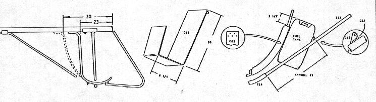
However,
for those "who have already made the
conversion and
those who probably
will (in
spite of our
recommendations), we
 suggest that,
as a minimum,
you rivet
on a two root wide doubler of .020 -
2024-T3 aluminum alloy over the leading edge of the D-Cells
under the Nacelles.
suggest that,
as a minimum,
you rivet
on a two root wide doubler of .020 -
2024-T3 aluminum alloy over the leading edge of the D-Cells
under the Nacelles.
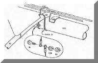
6.8
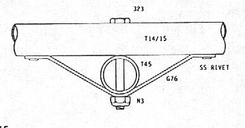
AXLE GUSSETS FOR RUDDER PEDALS
In the
assembly manual for the rudder pedal kit, there is a reminder that when
one rudder pedal is pushed down, the
other one must come up, and therefore you should not attempt to push on
both pedals simultaneously. However, for whatever reason, people do
occasionally push down on both pedals.
While reasonable pedal
pressure does not cause a problem. excessive force will bend the two 323
bolts which hold the nosewheel axle to the side tubes.
To alleviate this problem, we are now including with
the rudder pedal
kits two small gussets
(G76J to help
support the axle. If
you have an earlier rudder pedal kit and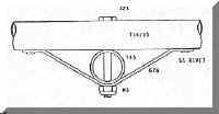 wish to add these gussets, you can make them yourself from two strips of
aluminum alloy .040 to .080 inches thick.
1/2 inch wide and 6 inches long.
Bend and install the gussets as shown.
wish to add these gussets, you can make them yourself from two strips of
aluminum alloy .040 to .080 inches thick.
1/2 inch wide and 6 inches long.
Bend and install the gussets as shown.
6.9
Muffler Outlet Angle
Although
the velocity stacks reduce the amount or oil buildup on the wings
considerably, you may still get a bit
or residue
on the
wings from
the exhaust if you have the new Nacelle mounted mufflers.
This can be greatly reduced by bending the exhaust exit tube in the
muffler upward about 15 degrees. To
do this.
simply fit a 3/4 inch diameter rod or pipe into the exhaust exit
tube and pull it upward to the desired angle.
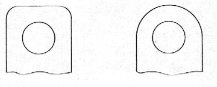
6.10
Front Fitting Radius
A
few kits were shipped recently with front fittings shaped as shown at
left below,
If you assemble
the control system
with the fitting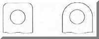 as shown, you will probably rind that it interferes with the pushrod when
you move the control stick to deflect the ailerons.
as shown, you will probably rind that it interferes with the pushrod when
you move the control stick to deflect the ailerons.
To
work properly the fitting should be cut, filed or sanded as shown at right
above.
6.11
PAINT YOUR MYLAR?
If
you recently covered your Lazair in
Mylar and you don't relish the thought
or tearing
it all
off to recover
in Tedlar,
you may be interested in the following:
in spite or the fact that paint will not adhere well to Mylar, a
couple or owners have had relatively good success with it.
The testing which we did a year
ago indicated that
initial adhesion
was extremely poor
after a 48 hour cure. The
same test samples were re-tested about a week ago and while the adhesion
was not as good as we might like. it was acceptable.
If
you wish to experiment with paint on Mylar, we suggest that you let the
Mylar weather
for a couple
or weeks. then degrease it
with Lacquer thinner and paint it with a pigmented urethane (this appears
to be the best or any or the paints we tested). Although the paint should offer
some protection
against ultraviolet
radiation, for
maximum Mylar life it is
recommended that you still follow the guidelines in update 3 item - 3.11.
6.12
RECOIL STARTERS
It's
now almost a year since we started flying with Rotax 185 cc engines,
in general, the
reliability or this
engine has been
very good, but the operating life of the recoil starters has been
less than we would like. The
most common problem we have seen is premature wearing of the starting
pulley (this
is the
cast aluminum device
which mates with the
pawls - not the sheave on
which the rope is wound). The
shape and location or the wear pattern indicates that the pawls are
vibrating in synch with the engine. but vibration
testing with
an amplitude or l0g's
over a frequency range o 10 to 100 Hz. failed to detect any resonances.
Changing the rate or the pawl springs and adding rubber damping seems to
reduce the problem a bit, but not to
an acceptable level.
Evaluating a potential
5olution to this type or a problem Is very time consuming because
although we have had a few starters show signs of wear In the first 20
hours. Most will
last 80 to 100 hours
before exhibiting any indication or a problem. and It can take this
much running time to determine if any improvement has been made.
After
several weeks or changing, testing, and evaluating we have reached the
conclusion that the only way
to get rid of
the problems in the Rotax starter is to get rid of the Rotax
starter. A survey of
manufacturers and small engine mechanics indicated that the most reliable
recoil starter in
common use Is
a relatively cheap and
simple unit made by Tecumseh. We
have several of these starters undergoing testing at present. and so far
the results have been excellent. if
this starter proves to have the reliability we
expect. it
will soon become standard
on all
of our Rotax engines. In
addition to improved reliability. this starter also provides a couple or
other advantages: It has a
larger sheave which makes
it much
easier to pull
when starting the
engine, and the overall size is smaller than the Rotax.
This allows us to use a smaller engine mount which will
accept a close fitting molded engine cowl to reduce drag and improve
the appearance. The
proposed mounting system will use the same rubber mounts and mounting
pattern as we have used since late January 1982 (four mounts on top and
two on the bottom) so retrofitting the new starters should be
relatively easy.
For
those who wish to repair the Rotax starters when necessary. we will be
stocking parts.
For those
who would like
to convert to the new starter. we will make a retrofit kit
available as soon as the test program is complete and the necessary parts
are made. All dealers and
distributors will be notified as soon as
these retrofit kits
are available.
As a service to customers, these kits will be sold at our cost. and
the usual manufacturer and dealer markup will not be applied (when the
kits are purchased to replace Rotax starters).
6.
Engine Mount Angles
We have received two reports of
broken G42 engine mount angles (these are the large brackets which are
bolted directly to
the crankcase).
Although this
represents less than 0.2 of the mounting brackets in use and
therefore does not indicate a trend. a careful inspection of these
brackets should be included in your normal
pre-flight. Since we
will probably be changing to a different type of mount to accommodate the
new recoil starter, we expect to have a few surplus mount angles which we
could supply at no charge to anyone who
returns a broken one.
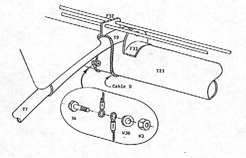
6.I5
Stabilizer Attachment
Approximately
a year ago we investigated a potential problem of broken F32 pushrod
guides causing the leading
edge of
the stabilizer
to become detached from the boom.
At that time, it was determined that it would be necessary to break
two F32 fittings to cause a problem. and even if this
did happen, the
stabilizer would be
held in position by
the T26 pushrods to permit a
safe emergency
landing. This
conclusion was substantiated by structural testing on the ground. flight
testing. and field reports.
However.
we have since received one report or F32 breakage. believed to be caused
by severe
lateral loading on
the tail
caused by side-slipping
- this was not
possible before the rudder pedals were incorporated). Fortunately. this
did not cause a serious problem and the aircraft made a normal landing,
but it
does renew our
concern. This
situation is not relevant to the newer kits which incorporate the folding
tail because the stabilizer is secured to the boom by the hinge brackets.
 However. if you have one of
the earlier
Lazair's and you intend to
execute some of the higher stress maneuvers possible with the rudder pedal
conversion, we suggest the use of a small safety cable wrapped around the
boom and T9 as an added precaution.
However. if you have one of
the earlier
Lazair's and you intend to
execute some of the higher stress maneuvers possible with the rudder pedal
conversion, we suggest the use of a small safety cable wrapped around the
boom and T9 as an added precaution.
6.16
Pushrod Rotation:
If
you have rudder pedals on your Lazair; you may have noticed that if you
push the stick as far as it
will go in one
direction. and push
the rudder pedals as far as possible in the opposite direction, then
reverse both to get full cross control the other way, the BE rodend on one
end of the T18 pushrod will rotate on
its threads about
twenty degrees. Since this
will happen only infrequently in service, the amount of thread-wear In the
P3 will not be appreciable. However.
you should be aware of this situation
and ensure that
the BE which
rotates is threaded into
the P3 at least half an inch. Check
the quality of the threads occasionally and replace the P3 if there is any
indication that the threads are worn.
|