Lazair Ultralight Aircraft Newsletter Number 5 June '82 |
|||||||||||
|
|||||||||||
|
The probability of survival is equal to the angle of arrival. |
|||||||||||
|
|||||||||||
|
|
|||||||||||
|
|
|||||||||||
|
|
|||||||||||
|
|
|||||||||||
|
|
|||||||||||
Lazair Ultralight Newsletter |
|||||||||||
|
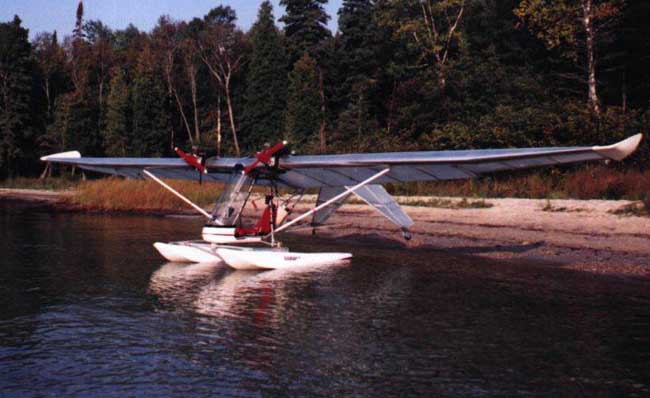
5.1 Lower strut plug installation Early Lazairs (the ones
with the spoked wheels) were designed so that the P16 strut plug
extended beyond the end or the
T27 strut tube. Later models (with
the "Tundra Tires") have a larger diameter axle (i~)ich
increases the spacing between the F6 gussets to 1 1/4 inches) and therefore
the P16 must be installed so that it is flush
with the
end or the T46 strut tube. If
you have one or the first few kits shipped after the changeover, your
assembly instructions regarding the position or the P16 may have been somewhat
ambiguous. Please check to make sure
that ~our P16's are installed as shown below, and there are two
315 bolts in each strut plug (P17's as well as P16's).
As a secondary check. you can measure If it is necessary to
reposition your P16 plugs, it should be possible to do so without having
to scrap either the
strut or the plug. ~whenever
possible. use existing holes in the strut.
Rotate the~Pl6 and drill new holes in it as necessary.
Make sure the center or the lower strut hole is at least 1/2
inch from the end or the strut. 5.2
TINY Bubbles IN THE LINE Now that we have
eliminated the primer bulb. the in-line filter, and the tee fitting. the
problem or bubbles in the
fuel line should be
gone forever - but now we have round a new source or bubbles - this one
even more intriguing than the others. After one or our factory demonstrators displayed some noticeable bubbles. we checked the fuel line for leaks and determined that there wass no place where air could get into the line - this is the main advantage or the submersible fuel filter. Since the bubbles appear to emanate from within the fuel itself, it has been determined that the bubbles are not air, but vaporized fuel. The exact cause or these bubbles is difficult to determine, but it is believed that water in the fuel effectively plugs the filter. Then each time the diaphragm in the fuel pump is pulsed there is a momentary reduction in pressure in the fuel line. This reduction in pressure lasts for only a fraction or a second, but it is sufficient to cause a small amount of fuel to vaporize and form a tiny (almost invisible) bubble. These gradually merge to form larger bubbles as they migrate toward the carburetor.
This
theory has not been proven, but it has gained credibility when the fact
that any time the problem
has occurred, it has been
eliminated (completely) by removing the felt from the fuel filter and
rolling and stretching it to get rid or the water. We
are now investigating the use or other materials (such as a brass
screen) to eliminate the
felt filter. In the meantime,
check your fuel lines for bubbles frequently while flying.
Check your filter periodically (especially if you suspect there
may be water in the fuel). Roll
the felt between your hands, stretch
it, compress it and then put it back on. 5.3
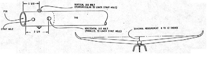
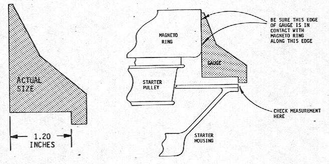
CENTERING THE STARTER ASSEMBLY To
prevent possible damage to the starter pulley on the rotax engine, it is
essential that the starter
pawl assembly be centered properly.
If you remove the
starter assembly from the engine or if the engine is removed from the
engine mounting assembly, the starter assembly position should be
checked after re-assembly as follows: First,
make a measuring gauge from thin sheet metal as shown.
Use this gauge to
check the radial spacing between the
starter housing and the magneto ring.
Check the spacing at four places (approximately equally spaced)
around the 5.4
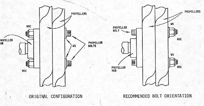
PROPELLER BOLTS Since the introduction or the rotax engine in November '81 we have had three reports or broken propeller bolts. After examination, it was determined that one or these failures was a result or the engine being run for a considerable length or time with the propeller bolts loose. The other two resulted Prom the propeller bottoming on the crankshaft nut rather than seating properly on the hub. A special notice regarding this potential problem and a suggested method or checking the depth or the counter bore in the propeller was mailed to all owners or kits shipped prior to January '82 (those who we thought could have experienced this problem) but it appears that some or the notices either did not reach their destination or were ignored by their recipients. Please check the installation or your
propellers and ensure that they are properly seated on the propeller
hub. The depth
or the counter bore may be
increased slightly if necessary to allow the propeller to fit properly
against the hub.
To
reduce the possibility or a bolt failure (even if a propeller is improperly
installed) all kits shipped after May 17, 1982 have the bolts inserted
through the hub in the opposite direction to that in This requires drilling
out bolt which goes
through configured, the bolts were the
holes in the propeller hub to 5/16 inches diameter, and allows the part
of the hub (where
the stress is highest) to be the full diameter.
As originally threaded into the propeller nub. The threads on the bolt
not only reduce the cross sectional area of the bolt by approximately
forty percent, but they also introduce a stress concentration, which, under
fatigue loads, can be as high as 2.7 to I.
By reversing the bolts, the threaded part of the bolt is moved
from the area of maximum stress to
the area of minimum stress.
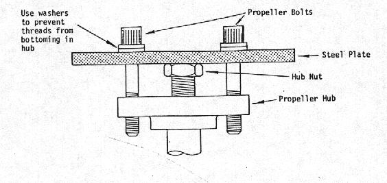
To
insert the bolts as recommended, it will be necessary to remove the
propeller hub from the crankshaft.
If you don1t have a gear puller, the following method
may be used: First, loosen the crankshaft nut and screw it off until it
protrudes about 1/16 of an inch past the end of the crankshaft, then
remove the propeller hub using a puller made from 1/4 inch steel and the
two propeller bolts as shown. If
you don't have a piece of steel handy, you can use one of your nacelle
weights and drill a couple of 3/8 inch holes in it.
Tighten the two
bolts alternately, slowly
To reinstall the
propeller hub, make sure the taper on the crankshaft and the hole in the
hub are absolutely clean and free
of grease. Apply a small amount of Loctite 242 or similar locking compound,
fit the hub onto the shaft and tighten the nut to a torque of 35 root
pounds. After the propellers are installed, the NSC propeller nuts should be tightened to a torque of 15
foot pounds. 5.5
UP YOUR CABLES In update number 2 we
discussed the problems of catching long grass in the cables.
To alleviate this problem, all
new Lazairs have the cables attached to the stabilizer at the end of the
spreader (TlI or TilS) rather than at the lower (outboard) corner as was
done originally. If you wish to modify your Lazair to move the cables uo~ it
is a relatively easy change provided that you have access to a Nicopress
tool and sleeves, since the cables must be shortened.
If you can't locate a tool readily, check with your local EM
chapter. 5.6
RUDDERVATOR PUSHRODS In a previous update
(item 4.4, December '81) we reported on a potential wearing of the T26
pushrods where they pass through the F32 pushrod guides. To alleviate this situation, kits shipped in May and 3une of
1982 included a roll of 5421 or 5423 abrasion resistant tape.
We have been flying factory demonstrators
with this tape installed for over four months and have not
encountered any difficulties. However,
if the tape is not properly installed, or if it becomes damaged (by
mishandling while assembling or trailering the aircraft) there is a
possibility that it could come loose and get wedged in the F32 making it
difficult to move the ruddervator pushrods. Although this has not
happened, the possibility does exist.
Therefore, if you
have the tape on your
aircraft, it is recoemended that the tape be recoved from the pushrods
and discarded. If you
received the tape with your kit, but nave not installed it yet, don't.
5.7
D-CELL NOSEERIBS The owner of a
highly modified Lazair reported recently that several of the foam
noseribs inside his D~el1 had moved out of position.
This was one of the earlier kits with the .016 inch D~ell skin,
(kits A192 and subsequent have a .020
inch D-cell skin) and was fitted with relatively heavy reduction units
and very large propellers. Although this is believed
to be an isolated case, it is recommended that all
owners check the position or their nose ribs occasionally
(especially in the area or the engine nacelles).
This can be done easily by tapping along the top or the D-cell
(about 4 inches ahead or the main soar) and listening for the ribs. There
should be a rib every 4 inches. if
you should ever get an indication that two or more adjacent ribs are out
or position, drill out a few rivets so that the D-cell skin may be
lifted sufficiently to look inside (with
the aid or a flashlight). Any displaced ribs should be
repositioned and bonded in place with panel adhesive.
To avoid loosening the D-cell skin, remove only as 'many rivets
as necessary and use tools made
from coat hangers to fish the ribs into position. It should be noted that
because of this possible problem, the use of Rotax engines on a Lazair
with .016 inch leading edge skin is not recommended. 5.8
CARBURETOR STUDS In spite of the fact that
carburetor studs are installed with Loctite and the carburetors are
attached with metal to metal shake proof nuts,
we have had three reports of carburetor studs or nuts working
loose on the Rotax engines. while
it is unlikely that this would ever cause a carburetor to
fall off , it could
become loose enough to
cause an engine to stop. To
lessen the chance of studs becoming loose, make sure the carburetor nuts
are tight. They should be retightened after the first few taxi
runs, before
the first flight,
and at least once every 20 flight hours thereafter.
Tightening the carburetor nuts can be made much easier if you
modify a 10 mm wrench by making a 45 degree bend in it about 1 1/2
inches from the (open) end. 5.9
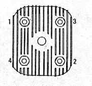
CYLINDER HEAD NUTS As
with any engine, the head nuts on the Rotax recommended that
this be done after taxiing nuts should be tightened in the
sequence shown engine should be
re-torqued after the break-in period. When re-torquing the nuts, they should be torqued to 17 foot-pounds. If a head has been removed, or the nuts are very loose, tighten all the nuts to 5 foot pounds each (using the sequence above), then to 10 foot pounds, then to 17 foot pounds. 5.10
ADDITIONAL AIRFRAME CHECKS Note: In 1982 a completely revised Lazair assembly manual was introduced. For the benefit of those owners having earlier revisions of the manual, some selected paragraphs from the new manual are reprinted below. If you have completed your Lazair, you may wish to check the items listed below, but note that this information is provided as a guide only. If you are satisfied with the way your aircraft riles, it is not necessary to make changes based on these checks, however, you might rind the information useful if you plan to make any other changes. 5.10.1
BALANCE (CENTER -OF- GRAVITY) CHECK Flight
testing has shown that the
Lazair is very tolerant or changes to
the position
or the center-of-gravity.
However, for comfortable
hands -off flying at a reasonable airspeed. and for assurance that there
is no gross error effecting the center-of-gravity, the check outlined
below is recommended with the center-of-gravity positioned as desired,
the Lazair should trim out hands-off at approximately 25 to 28 ~H
indicated airspeed. With the seat positioned
as indicated in the Assembly Instructions, the pilot sits very
near the center-of-gravity, so reasonable differences in pilot
weight do not have an appreciable effect on the position or the
pilot's feet, or even the type or shoes he is wearing. Minor in-night
adjustments to the
position or the centre-of-gravity can be made by just moving the
position or your feet. Also, there will be an effect from the weight or the fuel, so
it is recommended that the following check be made with the
fuel tank approximately half full. With the aircraft on the
ground and the pilot sitting in the seat in the normal (or most comfortable)
seating position, raise the
tail until the boom is level (use a spirit level).
Hold the aircraft in this position with a bathroom scale under
the spreader (T115). The reading
on the scale should be between I and 5 pounds. If the aircraft meets
this requirement it is adequately balanced for the first test fight (If
possible the first fight should be made by an experienced Lazair pilot
who is capable or recognizing any unusual
flight characteristics). Fine
tuning or the balance is best done by flying the aircraft and
adjusting the centre-of-gravity for hands-on trim at the power setting
and airspeed preferred by the pilot.
5.10.2
AILERON DEFLECTION CHECK Move the stick as far as
possible to the right, making sure it is neutral
rore and art. Check that the
aileron deflecti 5.10.3
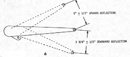
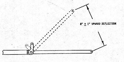
RUDDERVATOR DEFLECTION CHECK Push
the stick forward as far as possible.
The downward deflection or the ruddervators should be such that
they almost touch each other. Adjust the length or pushrod T18 as
required to achieve the correct downward deflection. Pull
the stick back as far as possible.
The upward deflec 5.11
AILERON BELLCRANK CLEARANCE Please
check the clearance between the 35 bolt holding the EE rod end to your
F39 aileron bellcrank (F39) and the spar cap
(reference drawing C in the parts catalog). Although we have seen
a problem in this area, a worst case tolerance buildup plus a slight
error in locating the bellcrank mount F38 could possibly combine to
cause the bolt to foul on
the spar cap. if necessary the spar cap should be bent slightly to
provide sufficient clearance. 5.12
FUEL TANK STRAP ROUTING When
the large (20 litre) fuel tank was introduced the assembly manual
indicated that the rubber
strap holding the tank in position should be routed over the top or the
tank and beside the large cap. As
most owners have already realized, an extra measure or safety can be
obtained by routing the strap through the handle on the fuel tank before
hooking it onto the T22's. 5.13
FUEL TANK SUPPORT RIVETS We
have had one report of loose rivets on a fuel tank support angle (where
it is riveted to the
T22's), after a series or hard landings. As a minimum, these
rivets should be checked on your walk around, and it is recommended that
they be removed and replaced by stainless steel rivets.
on older models the rivets would be those in FY and F30.
on newer models, (with the 20 litre fuel tank) this would be G62.
on newer models, it is also recommended that the bottom three
rivets attaching the fuel tank saddle, G63, to the seat back, be
replaced by stainless steel as an added precaution. 5.14
NACELLE MOUNTING BOLTS After three years of
production and hundreds or Lazair flying all over the world there was
never a report of nacelle mounting bolts working loose in flight
until last week when
we were told or two such instances.
Fortunately, the
renaming bolts held the engines on the wing but the possibility of an
engine falling off is obviously somewhat disconcerting.
Since the mounting bolts are threaded into nut plates
with an elastic stop nut feature.
The bolts should stay in place unless something degrades the
gripping action or the stopnut. Although the grip can be reduced
slightly with repeated insertion and removal of the bolt. Other factors such as the presence or grease or oil are
probably more significant. To make sure your bolts don't work loose, it is recommended that they be lockwired This may be done by replacing them with drilled-head bolts (type AN3H5A and AN43HA) or by drilling a small hole through the heads for the lockwire.
|
|||||||||||
|
|
|||||||||||
|
|||||||||||
| Ultralight Aircraft News Web Magazine Covering the World of Ultralight Aviation . You may link to these pages or print them out for your own personal use, but no part of this publication may be copied or distributed, transmitted, transcribed, stored in a retrieval system, or translated into any human or computer language, in any form or by any means, electronic, mechanical, manual, or otherwise, without the written permission of Ultralight News. By copying or paraphrasing the intellectual property on this site, you're automatically signing a binding contract and agreeing to be billed $10,000 payable immediately. Copyright Ultralight News | |||||||||||
|
|||||||||||