|
8.1
SPINNER MOUNTING FLANGES
We have had several
reports of fatigue failures in the spun aluminum flange (F81) used for
mounting spinners. Although
this may not be a
serious problem if it is noticed on a preflight inspection and
corrected, we have. had a report of a pilot receiving a foot Injury when
the whole spinner broke loose and flew off.
While part of
the problem
may be
due to an absence of loctite on the screws securing the spinner, or
an ~mproperly centered spinner, these are not likely the sole causes.
Mounting flanges which have
a larger
bend radius appear
to be
better but not
totally immune to fatigue problems.
Newer propellers have a large area on the rear surface machined
to fit onto the mounting flange, but some of the older propellers may
have some
slight interference with
the flange
from the trailing
edge of the blade and this should be filed as necessary to avoid
distorting the flange. We
are presently running endurance tests with a new design of flange.
When the testing
is complete,
the new
flanges will
be made
available at no charge to all owners who return the original
ones. In the meantime, It
Is strongly
recommended that
all spinners
and mounting
flanges be removed.
Until new flanges
are available, you can fly without spinners --- it doesn't look as good,
but the difference in performance isn't noticeable.
8.2
TAPE ADHESION
In
the past five months we have had four reports of loosening of Tedlar
covering, apparently due to poor tape adhesion. As
the reports are all quite different, there is no indication of
any one particular problem, and therefore determining the cause (and
remedy) is
not easy.
However, based
on the information we
have available, we can make the following suggestions.
(a)
Avoid overheating the tape (and
the Tedlar)
when heat
shrinking. As
stated in
the manual, overheating the
tape will cause it to shrink excessively and will lift it at the edges.
It is also probable that excessive heat will have an adverse
effect on the adhesive. Overheating
the Tedlar will
cause it to shrink excessively and could tend to pull it away from the
tape.
(b)
When cleaning the aluminum prior to the application of the tape
(whether on a new aircraft or when
recovering) use only
lacquer thinner as suggested in the assembly manual.
There is some indication (but no proof) that the use of acetone
for cleaning the aluminum may effect the acrylic adhesive
on the tape.
Do not use metal
cleaners (such as Met-All, Nev-R-Dull, Flitz etc.) as many of these are
designed to apply a protective coating as well as clearnthe metal.
These coatings
(especially the ones which contain silicones) can severely impede
tape adhesion.
(c)
Make sure there Is sufficient overlap of
tape on the
aluminum (as
described in
the assembly
manual), especially
along the D-cell and
along the root rib. If in
doubt, additional tape should be applied with at least 3/4 of an inch in
contact with the aluminum.
(d)
If there is any indication of Inadequate adhesion around the
perimeter of the Tedlar, some
of the
wide single face tape could be
removed and replaced, or additional tape could be applied as
In Cc) above.
(e)
Lack of adhesion of the foam tape on the ribs, while not a common
problem, could be a bit more difficult to
fix. We have only
seen this problem once, and the effected area was so small, it was just
left (though watched closely) and the condition has
not worsened.
If you
should ever
encounter this
situation (and
assuming you
don't wish to recover the wing), you could rivet an additional
aluminum capstrip to the effected ribs on the outside of the covering
(similar to C4
on the wingtip').
However, if you do this, be sure to put at least one layer of 1
1/2" or 2" tape over the Tedlar before the capstrip Is put on
and use double face tape under the capstrip.
Be sure
to file or
sand the edges of
the capstrip so they do not cut Into the covering.
In any case, do not (as one customer suggested) attempt to rib
stitch the Tedlar. Rib
stitching a
non rip-stopped material could
potentially create
many more
problems than it could cure.
While the additional capstrip suggested above does necessitate
drilling rivet holes through the covering, the
stress on the
covering is
distributed by the
relatively large area of the capstrip.
If rib stitching were used, the stress would be much higher due
to the small diameter of the rib cord.
(f)
If you paint your Tedlar and/or tape, use a light colour.
There is some indication that painted
a dark colour. and
left in direct sunlight for a prolonged period, the covering creep under
the tape due to the extremely high temperature developed.
It is may tend to
(g)
To check for overshrinkage on your wings, put a straightedge on
the trailing edge and measure
the deflection of the T25 trailing edge tub& between each
pair of ribs. A deflection
of one sixteenth
of
an inch is about right. An
eighth of an inch is excessive but acceptable.
A quarter of an inch deflection indicates that the particular
panel has been overshrunk. The
covering and tape on
that particular panel should be inspected and watched very
carefully or replaced.
(h)
An inspection of the covering and tape should be included in
every preflight.
The following two
paragraphs have been added to the assembly manual, and should be
observed if
you recover your Lazair'Ę:
"As with most
acrylic adhesives, the initial tack with this tape is only moderate, but
the adhesion improves as it
ages. For this
reason, it is essential that the tape be firmly pressed down to make
sure there is 100 percent initial contact. Then, as the adhesive cures, a proper bond will
develop."
"Unlike Mylar and
most other heat shrinkable covering materials, Teldar will continue to
shrink significantly after
the heat source has been removed.
Therefore, to avoid overheating the Tedlar, apply the heat for a
few seconds, then remove it and check for signs of shrinkage.
If there is no indication, heat it
a bit longer, then
remove the
heat and check again
for shrinkage. As the
heating period is Increased, you will find the correct exposure so most
of the shrinkage will occur after the heat source has
been removed.
If the heat is maintained
on the
Tedlar for a
significant period of time after it begins to shrink, it is possible to
overheat the material
and reduce the adhesion of the tape."
8.3
ENGINE INSPECTIONS
We have received one
report of a Rotax engine stoppage becausd the small wire between
the magneto
coil and the
condenser was
routed improperly
and contacted
the rotating
flywheel. Although this is
an unlikely
situation,
we will be checking all engines before they are
shipped to ensure that the wire
routing is correct. Engines in the
field can be checked quite easily if the engine is removed from the
nacelle. The flywheel does not have to be removed since it has
cutouts through which the wiring may be inspected.
We
also know of two engines which made rather ominous noises when
the crankshaft was rotated because the
polefaces on the lighting coil were rubbing on the
flywheel, so it might be wise to also check that the two screws securing
the lighting coil are tight. This can also be done without
removing the flywheel.
8.4
COMPRESSION RELEASE
We
recently received the second report of an engine being damaged because
it ingested the valve stem from the compression release.
To preclude
the possibility of this happening on one of your engines, we
suggest you pry off the little green plastic cap and inspect the quality
of the riveting which holds the aluminum
button onto the
valve stem.
If there Is any sign of weakening or bad riveting, the
compression release should be replaced.
The plastic cap is not required and may be left off to permit a
check of the
compression release
in every preflight inspection.
8.5
RUDDERVATOR PUSHROO ROTATION
Item
6.16 in an earlier Tech Update described a problem where the BE rodends
tend to rotate in the
P3 plugs during cross
control of
rudder and aileron. This
problem has been eliminated on the Series III Lazair~ by the use of a
totally different control linkage, but if you have one of the earlier
models with rudder pedals,
you can make two relatively
simple changes. First,
replace the large diameter S675 spacers supplied with the earlier kits
with the small diameter S344 spacers used on the Series III kits (with
W3H washers added to make
up the required length).
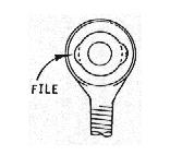
Secondly,
the allowable rotation of the ball can be increased
by inserting a 3/16
inch diameter chainsaw file through the pinhole in the ball and
carefully filing out a small section of the
ball retainer as shown.
Only a very small amount of metal needs to be removed, so don't
file away any more than necessary.
8.6
FUEL FILTERS
That
little white plastic cover on the bottom of the carburetor on the Rotax
engines contains a small
filter screen. This
should be removed and inspected (and cleaned if necessary) after
the first few hours and every 50 hours thereafter to verify that the
fuel filter in the tank is doing its job.
The
problem with the felt fuel filters described in Tech Update Item 5.2
appears to have been
eliminated by the
elimination of the felt fuel filters.
The newer kits are supplied with an all metal screen-type filter.
8.7
AXLE WEAR
If
you're still flying one of the very early Lazair's (the ones with the
spoked wheels) you should
pull the wheels
off at least once
every 50 hours and check the 4130 steel axle tubes for any indication of
rust, wear or any other condition which could lead to failure.
We have had two reports of axle breakage resulting
in a sudden
and extreme Increase
in dihedral. In one case, the airframe had been highly modified by a
previous owner and the steel axle had been replaced by a small diameter
aluminum rod with a cross-drilled hole
in it prior to the failure.
The other one, however, appears to be a failure of the original
axle tube
caused by wear
as a result of a wheel
bearing seizure. In lieu of
the frequent disassembly and inspectl9n. the axle could be replaced by
the later double wall large diameter aluminum one with the tundra wheels1
or a 1/8
inch stainless steel cable could be installed to keep the A-frame
from spreading in the event of an axle failure.
8.8
ROTAX HEAD GASKETS
There
is an indication that the head gaskets on the Rotax engines may compress
unevenly if the head nuts are
repeatedly retorqued1 and
this could eventually result in a cracked cylinder head.
Retorquing the heads once or twice during the first few hours of
operation is not uncommon, but if you find
it necessary
to retorque the
head 3
or 4 times, It
is strongly
recommended that you
replace the head gasket. The
recommended tightening sequence and torque value are given in Tech
Update Item 5.9.
8.9
SWITCH CONNECTOR INSULATION
The
following note regarding the terminals on the magneto switches has
been added
to Step
8.2.10 in
the latest revision
of the assembly manual. Please
check this on your Lazair'" ahd make the recommended change if
necessary. "Make sure
the plastic insulator is properly positioned after crimping. If it appears
loose, use electrical
tape or plastic
sleeving to ensure that the terminal cannot contact the F55 switchplate." A short piece of fuel line slipped over each terminal
can provide
additional protection
against accidental
grounding of the magneto wire.
8.10
OIL FOR YOUR ROTAX
In
the operating manual provided with Rotax powered Lazair
kits, we recommend the use of
mineral based two cycle
oil mixed
in a
ratio of
25 to
1, and do not recommend the use of synthetic lubricants which are
usually mixed in much lower concentrations.
This advice is based
on information
supplied by
the engine manufacturer, on
our own testing and experience, and on feedback from customers.
Although some owners have been using synthetics for a
considerable length of time with apparently
no problems,
others have
reported mysterious power losses and incipient seizures believed
to be a result of inadequate lubrication.
8.11
GROUND ADJUSTABLE PROPELLERS
Although
most Lazair
owners are
familiar with
situation regarding the
ground adjustable
props, the following is provided for the information of
those who have heard
only half of the story.
Following over a year and
a half of development,
we finally
began shipping
our composite
blade ground adjustable
propellers in June of 1983.
In mid July we received a call from a customer who described in
vivid detail what happened when one of his propeller blades separated in
flight. Because of the
very real
danger presented by
this situation
(and because
there was nothing obviously different about his propeller which
could explain why it failed and the others with hundreds of hours on
them did not) the decision was
made to initiate
a 100
percent recall of
all the ground adjustable propellers.
This decision was not made easily, but it was made quickly and
every Lazair owner who had
been shipped this
propeller was
personally phoned
and asked
to return
the propeller
(or part of it) to the factory.
Customers who had received the ground adjustable props in their
Series III ktis were sent the proven carbon fibre bi-blade props as
replacements, and customers who had
purchased the
ground adjustable
props for retrofit were offered a cash refund.
As you
might imagine, the cost of this
decision was substantial. (continued
next page)
Including the
development costs
incurred during the
past year
and a
half, the cost of tooling, the production costs of the propellers
which have now been destroyed, the cost of the replacement bi-blade
props, and administrative costs associated
with the
recall, the bill
came to over forty three thousand dollars. While this may seem like a small price to pay if it can avoid
a serious accident, it is not an insignificant amount to a company the
size of
Ultraflight (sometimes
we like
to think big, but we're not exactly General Motors).
It should be noted that the incident mentioned above was the
first (and the only) blade separation on one of our
production ground
adjustable propellers.
The recall
was issued
not because we felt there was a high probability of a second occurrence,
but because the possible consequences of a failure are so severe.
A failure of a wooden prop or even
a small
composite prop like
our bi-blades
can be frightening and is certainly not without danger, but there
is usually enough propeller left after the failure to limit the
unbalance to some degree. However,
when the ground adjustable
blade separated,
one whole
blade came off,
resulting in a horrendous unbalance --- sufficient to tear the engine
off its mounts, rip off both ground cables (which are rated at 600
pounds each in
tension) and
pull out the
magneto wire
so the engine could not be switched off.
Only the throttle cable was left to support the engine and thi
served only to allow
the engine
to flail
around like
a guillotine
on a
string. Fortunately, the
pilot, who
has had
many years
of flying experience, was able to retain his composure, control
the aircraft and shut off the engine with the choke, and he was able to
land safely. However, if
you can visualize yourself
in this
situation, you
might understand why
we took the only action which could positively prevent a recurrence.
The reaction to the recall has, for the most part, been quite
good. Almost every
owner agreed to
follow our
instructions and stop using the propellers.
Many even said "Thanks for telling me".
However, two Individuals have resisted our attempts to dissuade
them and are continuing to
fly with the
ground adjustable
props. We
care about your
safety. We care enough to
spend that forty three thousand dollars to help preserve it. If you
don't care, there may not be much we can
do about
it ---
but we will
continue to
try. In
the meantime, we are
investigating other avenues to try to get a bit more efficiency out of
the propulsion system. Many
wooden props of various shapes, lengths and pitches
have been tested
and while some are certainly satisfactory, none has been
outstanding, and so far not one has been able to match the
thrust-to-noise ratio which was obtained with the ill-fated
ground adjustable
prop. However,
our efforts are continuing and as improvements are made, you will be
notified.
|