
Rotax Bosch ignition wiring diagram
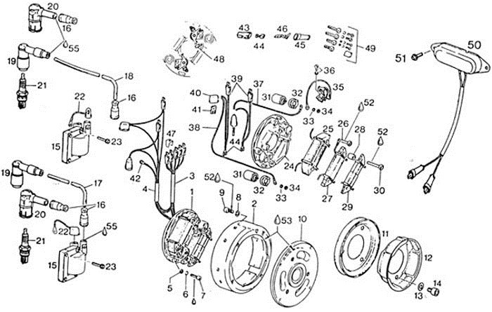
One other problem that has cropped up from time to time is the incorrect installation of the ground and magneto wires on the two poles on the ignition coil, on the points equipped engines. On Rotax engines these wires are locate on opposite sides of the coil, for each cylinder.
They are numbered 1 and 15.P On air cooled Rotax engines/B the coil should have the ground wire going to 15 on the PTO side and the magneto points wire going to the 1, while the recoil (mag side) side cylinder should have the ground wire going to the 1 and the magneto point wire going to the 15.P
The ignition suppressor box on the air cooled Rotax engines is wired black to black, and red to red.
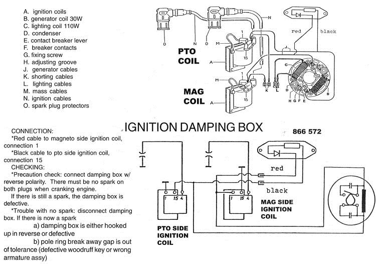
ON THE LIQUID COOLED 532 ENGINE, the coils are wired PTO side 1 to ground, 15 to points, Recoil (Mag side) 15 to ground 1 to points. P On the 532 the ignition suppressor box is wired BLACK TO RED, AND RED TO BLACK.
During regular preflight it is recommended that the pilot check the ground wires, and the bolts retaining the coils to the engine. The pilot should be looking to see whether the bolts have loosed off, which could result in a coil falling off, or ground wire loosing ground, or to see if the ground wire, where it enters the connector used to retain it to the bolt, is broken or frayed.
This is caused by the air turbulence around the wire causing bending it back and forth, which over a period of time results in failure of the end where it connects to the wire.
Rotax Bosch Ignition wiring
If a coil is removed for any reason, or the retaining bolts are found to be loose, they must be LOCTITE (using purple 222 loctite) back in. To simply retighten them is asking for problems, since these are self threading bolts, and generally pull threads when they back out.
Another reported problem encountered by pilots with the ignition system on the Rotax engine is in the connecting of a tachometer to the two black leads used to shut the engine off. When connecting a tachometer to the Rotax engine connect it to the two green leads coming from the magneto. These leads are usually connected to two yellow leads, making for a yellow/green, yellow/green combination. To connect the tachometer simply separate the two green leads from their two yellow counterparts and connect the tachometer leads, to two greens.