

Troubleshooting the Rotax ultralight aircraft engines.
Return To Ultralight News Main Index
Rotax Two Stroke Aircraft Engine Troubleshooting Volume II
The primary two stroke engine used by current manufactures of ultralight aircraft, in both the United States and Canada is the Rotax engine. This engine is available in horsepower ranging from 9 to 75. Parts and service is available through a vast network of factory trained service centers, and the cost, although creeping up, is still within reason. Another factor contributing to its success is that it can be purchased as a complete propulsion package from one supplier.
The primary two stroke engine used by current manufactures of ultralight aircraft, in both the United States and Canada is the Rotax engine. This engine is available in horsepower ranging from 9 to 75. Parts and service is available through a vast network of factory trained service centers, and the cost, although creeping up, is still within reason. Another factor contributing to its success is that it can be purchased as a complete propulsion package from one supplier.
Exhaust, carburetor, fuel pump, prop and reduction drive are all obtainable, in various exhaust configurations and gear drive combinations. These factors have all contributed to its acceptance by manufactures and pilots. But like any other product used in today's market, especially one where the use is so varied, problems have occurred.
Some of these problems can be traced directly to the manufacturer of the ultralight, others to the owner, and others to the engine. In an effort to make more pilots aware of some of the associated problems, and their possible solutions, the following is a synopsis of reported problems encountered by Rotax engine users, and some possible solutions.
These are general problems found in most cases with all the Rotax engines, in further reports we will deal with each engine separately.
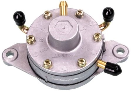
Fuel Supply: The Mikuni fuel pump is the primary pump used in the ultralight industry, and with the Rotax engine.
The following is a list of items to be considered and adhered to:
- When mounting the pump make sure that it is no more than 11 inches away from the impulse outlet on the engine.
- Make sure that it is mounted away from any heat source, and that it is positioned so that the vent on the pump face is facing down.
- The vacuum line used to connect the pump to the engine impulse outlet is of a much thicker wall thickness than regular gas line, and is not effected by heat.
- The gas line and vacuum lines are generally exposed to sunlight in most older configuration of ultralights and it is suggested that they be checked on a regular basis for cracks, discoloring, or UV deterioration (Yearly replacement is a good preventative maintenance approach). All lines should be carefully clamped, with clamps that do not pinch the line.
- The fuel system should have some kind of a water trap, this can be as simple as a loop in the line used to join the two gas tank halves together on a root tube mounted tank.
- A proper in line filter with a drain cock, or a pickup line located an inch from the bottom of the tank.
- During initial installation of the tank it should be inspected to make sure that no plastic is present, inside, from the drilling of holes, or from the manufacturing process. More than one pilot has had to land with an engine out only to discover plastic lodged in his fuel pump.
- A fuel filter should be installed in the fuel system prior to the pump to prevent any foreign material from entering it. If for any reason the filter is removed and is going to be reused make sure that the direction of flow is the same as when it was removed. Several pilot has reported re-installing their fuel filter backwards, depositing all the foreign material collected directly into their pump and carburetor. Most quality filters have arrows showing the direction of fuel flow.
- When considering fuel tank location, try to make it as close to the engine as possible with the least amount of vertical draw. Although the Mikuni pump has been known to draw fuel vertically over 4 feet the recommended maximum distance is only 24 inches.
- Make sure all tanks are properly vented. Many ultralight manufacturers use a standard marine fuel tank, with a vent on the handle (or gas cap) that can be screwed in to seal for transportation. The problem here is that the vent can vibrate closed, or can be inadvertently left closed. This allows the engine to run for a short period of time before it runs out of gas, just about the time your 50 feet in the air. Another problem is with gas caps that have a small pin hole in them for a vent, this holes should be checked to make sure it hasn't become plugged. If you have one of these tanks a solution is to drill a small hole in the handle, at its highest point. Another problem with some of these tanks is that they have a steel check valve located in the tank fuel outlet, in some cases this ball is to heavy for the Mikuni fuel pump to lift completely, causing a fuel starvation problem.
- Make as few restriction in your fuel system as possible. Some pilots have installed electric fuel pumps into their systems, in addition to the Mikuni pump. There are several potential problems with this. First the electric pump is capable of producing considerably more pressure than what the fuel system is set up for. Secondly when the pump is turned off it is an added restriction. One other commonly reported problem is in foreign material entering the system. This can be plastic from the manufacturing process, or simply cork lining used to seal the gas cap. Before installing any gas tank make sure that it is clean and free of any debris.
Fuel: The recommended fuel for the Rotax engine is PREMIUM UNLEADED, mixed with a GOOD QUALITY two stroke oil, the recommended mixture is 50 to 1. Fuel containing up to 10% ethanol can be used! Just remember that the fuel travels through a variety of things before it enters the engine! These other parts may not be able to handle ethanol!
For best performance this fuel should be fresh, and under no circumstances should premixed fuel be stored in bulk for any length of time, as the oil tends to reduce the octane rating of the fuel in storage.