|
The energy rating is determined by the disc weight. Exceeding the energy capacity of a braking system leads to excessive disc temperatures. This can cause low friction coefficients and reduce brake torque and aircraft deceleration. Permanent damage to the disc can result in the form of warping or loss of corrosion protection.
Brake Torque
The second rating is for brake torque. The rated torque value is used to determine the deceleration and static torque for engine run-up that will be provided by the brake. A braking system using the same disc can have one energy rating but several torque ratings. This is possible by using different caliper configurations on the same disc. For example, a braking system using a single caliper on a disc with a 189K ft-lb rating may have a torque rating of 1980 in-lb. The same braking system using two calipers would have the same energy rating of 189K ft-lb but would have a torque rating of 3960 in-lb. MATCO mfg offers it's customers a wide range of caliper configurations and disc sizes to allow for meeting both the energy and torque requirements for their aircraft.
Getting the Rated Torque
The rated torque value assumes a nominally conditioned brake pad (see pad break-in instructions), rated pressure applied to the brake, free floating calipers, and pad contact on both sides of the disc. Brake pad conditioning allows a glaze to form on the pads and provides the highest friction coefficient and drag force. MATCO mfg brake torque ratings are based on 450 psi applied pressure. Pressures below this value will generated proportionally lower torque. Pressure above this value will provide higher torque although pressures above 600 psi generally cause caliper deflections that reduce the torque increase. The torque rating assumes that all caliper force is used to squeeze the brake pads against the disc. If the caliper does not float freely on the guide tubes, pad force may be lost. In severe cases where the caliper does not float freely, it is possible that only one side of the disc surface may be contacted resulting in 50% loss of torque.
Get the Pressure Right!
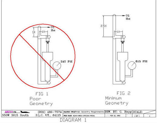
Assuming the calipers are properly mounted so that the pads make contact on both sides of the disc (both new and worn) and are maintained so that the caliper float freely, the most common reason for under performance of the brakes is low pressure. MATCO mfg brakes need 450 psi to achieve their rated torque. Additional calipers can be added to get higher torque at a lower pressure but it is often more weight efficient to modify the hydraulic system pedal geometry to generate high pressures. Systems using hand or foot operated master cylinders require a minimum of 2.5 to 1 mechanical advantage when using master cylinder, MC, like the MC-4 or MC-5 which have .625 inch diameter pistons. (Systems using MC-4 or MC-5 with intensifiers have .5 inch pistons and require a 1.6 to 1 mechanical advantage). Mechanical Advantage, MA, is the ratio of the force applied to the master cylinder shaft divided by the force applied by the hand or foot. Diagram 1 shows two
examples of pedal geometry. The first has a MA of 1 to 1 since the distance from the applied load to the pivot point is the same as the distance to the MC and is undesirable. The second shows a more favorable configuration that will easily provide the required pressure to the brakes with moderate toe force.
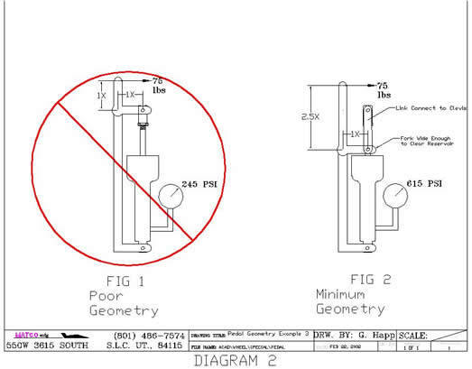
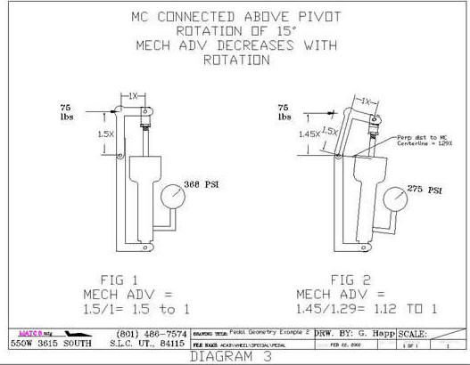
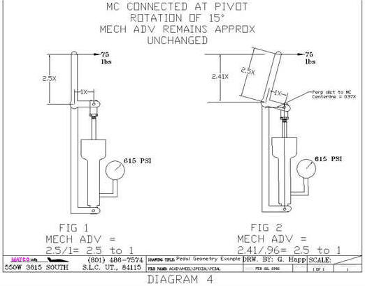
It is often necessary to keep the foot pedal shorter than that shown in Diagram 1. An alternative geometry is shown in Diagram 2. This design would utilize a fork arrangement on the MC connection to allow clearance of the MC body and then a short linkage to the MC connect point. A design common to many aircraft uses linkage as shown in Diagram 3. This design also allows for a shorter brake pedal but has a major disadvantage. This linkage can be configured to have proper MA in the start position (with the master cylinder fully extended). The MA varies with rotation however. As shown in Fig 2 of Diagram 3, a 15 degree rotation of the linkage reduces the MA at the start position from 1.5 to 1 down to only 1.12 to 1. In actual operation, this has the effect of causing a nearly constant brake torque even though increasing force is applied. For example, if the geometry is set for initial a MA of 2.5 to 1 in the start position and the pilot applies pedal force,
the MC will begin to stroke as pressure builds. As the rotation occurs, the MA decreases. If there is any air in the brake lines or if there are long brake line runs, hydraulic system expansion will occur as pressure increase requiring more MC stroke. If the pilot applies more pedal force, more MC stroke occurs, and the MA decreases further. Even though the pilot has now increased his pedal force, the force applied to the MC will be only marginally increased because more rotation will result and cause a further decrease in MA. A geometry like that in Diagram 2 will provide the same reduced pedal height and is not prone to the effect of rotation since the MC is essentially connected to the brake pedal pivot. Diagram 4 illustrates the benefit of pivot connect geometry during rotation. The MA remains virtually unchanged for expected rotation angles and results in a linear pressure increase with applied pedal force.
Heel Brakes
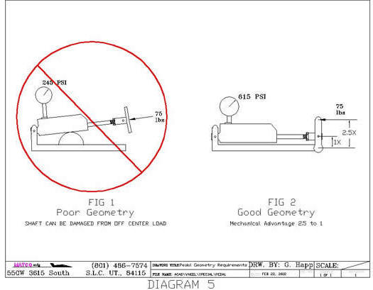
A common means of providing pilots with differential braking ability without resorting to the more complicated geometry of toe brakes is to use heel brakes. The same design requirement exists for the MA of a system using heel brakes as for toe brakes. It is not uncommon to see MC's configured to allow the pilot to apply heel force directly to the MC by means of a pad or button connected on the end of the shaft. This configuration is shown in Fig 1 of Diagram 5. The MA of this system is 1 to 1 and produces very low pressure for reasonable heel force. Perhaps a larger concern however is the potential for causing damage to the MC. The MC is designed to accept loads applied along the length of the shaft. Loads applied off axis or perpendicular to the shaft cause bending moments in the MC shaft that it was not designed for. Damage to the MC end gland, or bending of the MC shaft may result if the off axis loads are high enough. A more desirable configuration for
heel brakes is shown in Fig 2 of Diagram 5. This system uses a short linkage connected to the MC that provides the 2.5 to 1 MA while insuring that loads will be applied along the length on the MC and prevent any damage during actuation.
Conclusions
Like any system on an aircraft, the hydraulic system has many engineering options for providing the necessary requirements. Systems common on light aircraft must be engineered to provide adequate pressure to the brakes to achieve the rated torque.
MATCO mfg brakes require 450 psi to achieve the rated torque. The pedal geometry, whether hand, toe, or heel operated, requires a mechanical advantage of at least 2.5 to 1. This allows the pilot to easily generate the required 450 psi with moderate applied force. Pivot connected geometry provides the best means of accomplishing this requirement without the problem of rotational effect that reduce mechanical advantage.
|