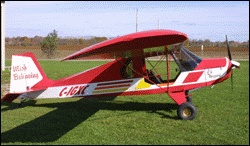
Answer: MATCO mfg wheels using tapered roller bearings are equipped with Timken bearings utilizing integrated grease seals on the bearing cone to ensure the longest possible life. The torqueing procedure for bearings with these type seals is different than for tapered roller bearings without them. A common torqueing technique for bearings without integrated seals is to tighten the axle nut until the wheel stops spinning freely and then back off to the nearest locking feature. THIS TECHNIQUE WILL NOT WORK ON A BEARING WITH AN INTEGRATED SEAL. The reason for a different torqueing technique is that the grease seal produces some drag and makes the wheel feel somewhat stiff when rotated. Reducing the axle nut torque until the wheel spins freely will allow the grease seal and the bearing cone to improperly rotate with the wheel (the cone must not rotate relative to the axle). The higher rolling drag is completely normal for this bearing and allows for
longer bearing life since the seal will keep most contaminants out. Timken specification state, for example, that the two 1.25 inch tapered roller bearing used on the WE51 will produce between 18-26 inch pounds of torque (drag) when properly installed. A light coating of grease on the seal will help reduce the drag on initial installation. The drag will also reduce after the bearings have been installed and the seal relaxes in the bore. It is important that the axle nut torque be sufficient to keep the seal from rotating with the wheel. With the bearings cleaned, dried, greased, and inserted in the wheel, the axle nut should be tightened until all play is out of the assembly. Rotate the wheel back and forth while tightening the nut to help seat the bearings. When all play is out of the assembly, and the wheel rotates freely, tighten to the next castle slot and insert the cotter pin. The rubber seal on the tapered roller bearing will remain stationary while the wheel rotates
around it. If the seal is spinning on the axle, the nut should be tightened further until the seal stops spinning with the wheel.
Question:
What do I do if one wheel drags?
Answer:
Check to be certain that pressure is not being applied to the brake by a blocked hydraulic line by loosening the bleeder carefully. If brake fluid under pressure is expelled and the wheel now turns freely, check the hydraulic line for the block source. If this did not free the brake, most likely the brake guide tubes are bound up by the brake plate anchor. Fix this by cleaning any rust deposits off and lubricating the brake guide tubes. Check to ensure that the brake plate anchor Is not deforming when the bolts are tightened against the axle head. Some shimming may be required to ensure a flat fit.
Question:
How can I fix leaking fluid around my brake bleeder seat?
Answer:
Use a thread sealant compatible with petroleum such as LockTite 567 Thread Sealant. sealant works well.
BRAKES
Question:
Why do my brakes feel spongy or weak?
Answer:
Check to ensure that there is no air in they system. Air can be trapped in any high spot in the line and often cannot be "pumped" out. Ensure no high spots during bleeding. The following bleeding procedure may be used:
A. Open brake bleeder valve slightly on the brake caliper to facilitate bleeding of air from the system.
B. Attach a tube from the nozzle of a squirt can (such as the MATCO squirt can part # MSCCHPSS) or bleeder tank of brake fluid, to the top of the brake bleeder valve. Pump the handle until oil flows bubble free from service hose before attaching.
C. Make sure that the master cylinder shaft is fully extended to open up the internal bypass valve.
D. Inject brake fluid (Mil-H-5606) or equivalent, into the puck housing and continue injecting until the fluid travels through the system in to the master cylinder.
E. Air in the system will be pushed up and out in to the master cylinder ONLY IF the master cylinder cap (if master cylinder has built in reservoir) or remote reservoir, if used, is at the highest point in the system, and there are no loops in the brake lines.
F. Fluid should be pushed through the system until it reaches approximately � inch from the top of the master cylinder or remote reservoir.
G. Close the brake bleeder valve, and remove the service hose.
H. If the brake system is free of air, the brake pedal should feel firm and not spongy. If not, repeat steps 1 through 7 until system is free of trapped air.
NOTE: Problematic systems (especially those with local high spots in the hydraulic lines) may be best bled using a vacuum source at the reservoir and hydraulic fluid supply conected to brake bleeder. Drawing hydraulic fluid up through the system often improves the removal of trapped air in local high spots. High spots may be in the caliper, master cylinders, fittings, or park brake valves.
Second check to ensure that your linings have been adequately broken in using a standard break in procedure. Your lining should produce a shiny transfer layer if properly conditioned. The following procedure should be adequate to condition the linings: 1) Apply brake pressure for high throttle static run-up. Note RPM at creep if any. 2) Perform 2-3 high-speed taxi runs (firm braking from 30-40 mph to 5 mph) to generate 300-400 degrees at brake pads. Do not bring aircraft to a complete stop during the taxi runs and also allow the aircraft to roll until back to the tie down area. Release brake pressure at tie down area as soon as practicable and park with brake pressure off. 3) Allow brakes to cool 10-15 minutes. 4) Repeat step 1. There should be a noticeable increase in holding torque. Repeat steps 1-3 if necessary. Properly conditioned pads and discs will have a uniform, shiny appearance on the surface.
Third ensure that the none of the o-rings has been damaged or is letting fluid out.
Fourth, check to see if you are getting adequate pressure from the master cylinders by attaching a pressure gage to the brake bleeder seat port and applying pressure. Pressure ranges from 300 PSI to 500 PSI are adequate.
Fifth, ensure that both linings are touching the brake disk. If both linings are not touching, check to see if there is adequate travel of the brake plate anchor along the guide tubes. When both linings are now, the brake plate anchor should be between the center line and the housing. See the caliper adjustment drawing for B3 & B4 brakes under Brake Assembly Drawings at www.matcomfg.com for more details on adjustment of those brakes.
MASTER CYLINDERS
Question:
Why does my MC-5 master cylinder is leak around the top?
Answer:
Overfilling is the primary reason for leaking around the shaft. Since the master cylinder vents around the shaft, the fluid level should be only 3/4 full to allow for master cylinder travel with the rudder pedals. The MATCO master cylinder is designed to function within fifteen degrees of vertical. If you cannot install within fifteen degrees of vertical, use a remote reservoir master cylinder.
Question:
What size fittings are used in the master cylinder?
Answer:
MATCO mfg. uses 1/8 tapered pipe fittings for all fittings.
Question:
Why does the cap on my remote reservoir have a vent?
Answer:
Your hydraulic system is designed to allow it to self adjust as the pads wear. This is accomplished by having a by-pass valve in the master cylinder that opens to the resevoir when the master cylinder is at rest and the shaft is fully extended. With the by-pass open, the reservoir is connected to the hydraulic system and allows fluid to flow into the portion of the system below the master cylinder and supply additional fluid required 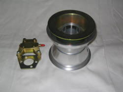 as the brake linings wear and the brake pistons extend. The fluid can only flow to the lower portion if the system is vented. For aerobatic use, the vent may be plugged but will need to be manually vented (cap opened) after 15-30 landings or the cylinder may begin to draw a vacuum and introduce air into the system from the master cylinder end gland shaft seal. as the brake linings wear and the brake pistons extend. The fluid can only flow to the lower portion if the system is vented. For aerobatic use, the vent may be plugged but will need to be manually vented (cap opened) after 15-30 landings or the cylinder may begin to draw a vacuum and introduce air into the system from the master cylinder end gland shaft seal.
For questions not covered here, contact
the MATCO mfg. technical support department at (801) 486-7574
between 7:30 a.m. and 4:00 p.m. M-F Mountain Standard Time
website: http://www.matcomfg.com/
e-mail .wheels@xmission.com
|