|
The troubleshooting is broken down
into several areas.
Now these problems will not show
up in all aircraft as updates to the XA were an ongoing thing. But many
early kits were sold to dealers who later went broke. Some of these kits
are just now entering the market. In the case of resale aircraft, there is
no way of getting update information to the new owner, unless he or she
has been in contact with the someone who owns an XA
Wing:
One of the first reported problems
with the first group of Buccaneer XA's off the assembly line was in the
wing. After less than six hours of flying in Canada, the trailing edge on
the wing bent up 18", about 30 inches out from the root.
This failure happened in rough
conditions, but in conditions that I would not be afraid to fly a Quicksilver MX in. After the failure was reported, Highcraft Aeromarine,
the original manufacturer, immediately sent a notification to all owners.
A retrofit kit was developed which put an inner sleeve in the effected
area.
Quicksilver MX in. After the failure was reported, Highcraft Aeromarine,
the original manufacturer, immediately sent a notification to all owners.
A retrofit kit was developed which put an inner sleeve in the effected
area.
Unfortunately when owners went to install the sleeve it was found
that their trailing edges were bent enough that the sleeve could not be
put in place. Highcraft then redesigned the trailing edge going to 1 1/2
inch tubing rather than 1 1/4".
They also upgraded the size of the
compression struts at this time. With the introduction of ailerons this
went to 1 3/4" in on inner sleeve out past the first set of wires.
The next problem with the wing was
with the stainless steel channel brackets used to attach the wing to the
root tube. After landing several pilots complained about loose flying
wires. It was discovered that the channel brackets had bent back, in some
cases over an inch. The factory updated to new aluminium bracket. These
brackets were also found on the tail section on the horizontal stabilizer
and rudder. This area was also updated to the new aluminium brackets.
Another problem found during
assembly of the wing kit was that the two cross
 brace wires running in an
X pattern from the leading to trailing edge were not tight. In some cases
the remedy was to turn one end of the wires counter clockwise until the
slack was taken up. In other cases the wires had to be redone. brace wires running in an
X pattern from the leading to trailing edge were not tight. In some cases
the remedy was to turn one end of the wires counter clockwise until the
slack was taken up. In other cases the wires had to be redone.
Other changes or updates to the
wing included, shortening of the wing tip, the addition of ailerons, to
replace the spoilerons, (which requires a new wing update kit, and the
wing fabric had to be sent back to the factory to be resown) and the
installation of lower battens in wing. The addition of the lower battens,
strengthened the wing and increased the aileron effectiveness.
Another update effecting the wing
was the replacement of the flying wire shackles. In addition to the
replacement of the shackle, a spacer was added, which fits between the two
shackle ends. Pilots have reported bending of the shackles, the spacer
prevents this. The new shackle is considerably stronger than the older
type.
Many pilots have reported that the
duck bills located at the end of the battens have broken off. This does
not present a safety hazard if the broken batten tip is replaced. If not
replaced it can result in the ripping of the wing fabric.
Another problem area on the wing
that has been reported is with the plastic saddles used between the flying
wires and the leading and trailing edge. Over time these crack and break
off. At the first sign of deterioration they should be replaced.
Index
Airframe:
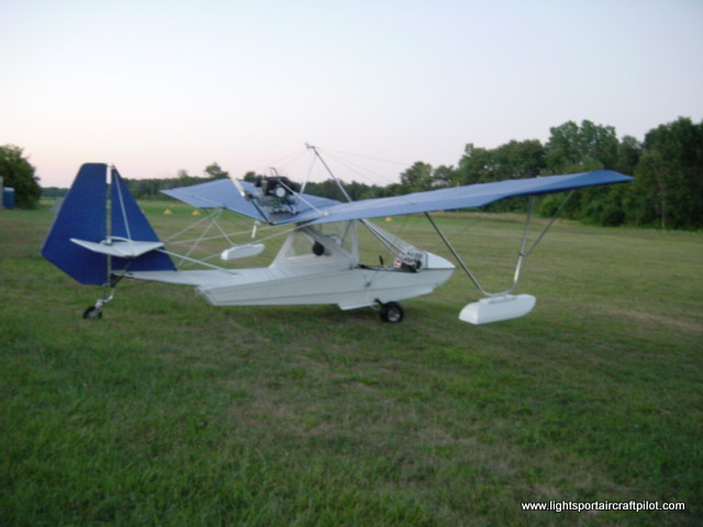
The Buccaneer airframe has proven
to be one of the strongest and most durable in the industry. Part of this
can be attributed to the fact that the hull and landing gear prevent shock
loads from being passed through to the airframe.
One of area that was updated was
the main upper boom running from just behind the pilot to the tail
section. With the installation of the heavier 377/447 engines, coupled
with rough field operation it was found that this tube would bend directly
below the engine mount, and/or where the leading edge of the vertical fin
attaches to the main tube. This was almost impossible to detect. The main
boom is covered with Dacron sailcloth and the bending takes place under
two plastic saddles. The problem was discovered when pilots started to
complain about a difference in pitch control, over a period of time. What
was happening was that with the tube bending it would change the angle of
incidence between the wing and tail.
To correct the problem, a sleeve
was added in the area that the main tube bent, and a set of support wires
were added running from the front upper bulkhead cross member to the lower
aft bulkhead. These cables then in effect help support the tube.
To correct the bending under the
vertical fin, the main tube was sleeved, and a bulkhead was added that
joins all three main tubes together in the area of bending. These solution
cured the problem.
Another reported problem was in
the aft vertical stabilizer tube. This tube was reported to crack or break
at the point where it joins into the lower tail section assembly. The
factory updated this tube by installing an inner sleeve.
Pilots have also reported that the
leading edges of their horizontal stabilizers have bent, in the centre.
This causes loose fitting fabric on the stabilizer. To my knowledge this
problem was not addressed by the factory. Our solution was to inner sleeve
the leading edge tube.
Probably the most potentially
dangerous problem of the airframe was with the main bulkhead. During
preflight several pilots have reported this bulkhead to have cracked
directly above a welded support gusset. The main bulkhead supports the
flying wires and landing gear. The factory solution was to extend the
support gusset farther up the bulkhead. This problem was discovered on
some models as late as 1989.
Another reported airframe problem
occurred in very early production aircraft using the 277 Rotax engine with
the Eipper style exhaust mounted to the kingpost. The problem, cracks
developing in the kingpost where the retention bolt was drilled through
the tube. The factory updated by first changing to a bracket that did not
require the king post to be drilled. Second by changing to a side mount
exhaust and completely changing the exhaust mount.
Index
Hull:
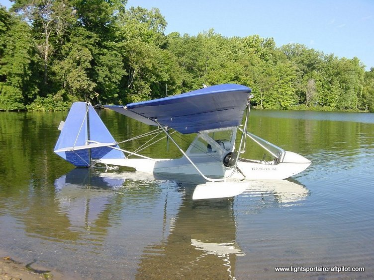
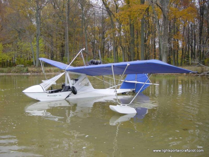
Due to the restriction put on the
manufacturer as far as weight allowance, the hull on the Buccaneer XA's
was built as light as possible to fit into the regulations. This
unfortunately meant that it was very easily damaged.
The area of damage occurs in
several areas, directly below the pilots feet, where two wood stringers
are located. Directly under the pilot seat, at the step. In the back end
of the hull.
The damage under the pilots feet
is usually caused by a hard landing. The impact separates the two
stringers from the fiberglass mat. This leaves only the outer skin and
gelcoat to support the craft.
Pilots in Canada strengthened this
area by first repairing the hull with glass and cloth from inside. Then
fibre glassing aluminium tubes (damaged Eipper nose struts, or rear down
tubes work great) into the hull directly beside the wood stringers.
The damage under the pilots seat
is caused by hard water landings or landing on a runway with the gear up.
To strengthen this area, first refibreglass the damaged area from inside.
Then mix a quart of fiberglass resin together with a pound of baking soda.
Mix well, then pour it into the step area. Be careful not to much hardener
to the resin, or it will cause the mixture to cure to fast and it will
crack. When this mixture hardens it turns to a rock hard substance, that
adheres very strongly to the hull.
The damage to the tail section is
caused when the craft goes in and out of the water. The sand, rocks, etc.
will wear through the hull. (As will a landing with the gear up on
pavement). This damage is repaired the same was as the step. Mix your
resin and backing soda together and pour it into the effected area.
One other thing, when doing the
tail section it is necessary to remove the styrofoam floatation from the
tail. We have found that this styrofoam can be a source of attitude
instability. In many cases where the craft has been sunk, or left out in
the open the styrofoam will absorb water. One chunk we took out of a two
year old craft weighed over 20 lbs.
Another problem reported in the
hull area was with the male and female Velcro used to attach the body sock
to the hull. This Velcro looses its "stickiness" when subjected to water,
or when continually removed and refastened. The Velcro section that sticks
to the hull has also been reported to become detached, especially if left
in direct sunlight.
If either happens this can lead
to:
- water entering the hull
- the body sock being sucked into
the propeller.
Our solution was to install an
aluminium strip over top of the Dacron body sock and Velcro strip,
fastening the strip by screwing it into the hull. This strip can be
obtained from local hardware, or rug stores. It is used to cover the end
of a carpet where it goes into a doorway. It has a nice little bend to it
and comes with its own screws. After installation we run a bead of silicon
along the seam between the aluminium and the hull for added protection.
Another update to the hull area
involved the rear section of the aircraft. Many pilots, and several
writers, who flew the aircraft complained about water entering the hull
during taxiing. To cure the problem a piece of foam was added that better
sealed the rear of the hull off from the water, and the three main tubes
were capped to prevent water from entering them.
Another area that was updated to
prevent water from entering the hull was the main gear support tube. It
was found that water would enter between the hull plate and hull gasket.
Siliconing this area help prevent the leaking. Later models came with a
rubber "inner tube" like material which fit snugly over the main gear
support tube and prevented leakage.
The gear leg stop was also
changed. This aluminium plug fits into the landing gear, acts as a stop
and prevents it from turning. The plug is held in place by a 1/4 inch
bolt. The original bolts were fine thread. It was found that these
stripped very easily and were later replaced by a course thread insert and
bolt.
Index
Control system :
The Buccaneer was originally
designed with spoilerons. The positioning and size of these was changed
several times, then finally eliminated to be replaced with ailerons.
YOU CAN NOT REPLACE THE SPOILERON
SYSTEM, BY SIMPLY ADDING AILERONS. THERE IS A COMPLETE RETROFIT KIT, WHICH
ADDS LOWER BATTENS, SHORTENS AND STRENGTHENS THE WING, AND REQUIRES THE
WINGSAIL TO BE RESOWN.
One of the problems reported in
the control system was with the rudder compression strut. It was found
that it would slide down inside the rudder covering. This caused the
rudder fabric to become loose. The solution was to install the strut, then
wrap several layers of tape around the leading edge of the rudderpost,
directly under the compression strut. This prevented it from slipping
down.
Another reported problem area was
with the rudder cable attachment clevis pin rings. Because the Buccaneer
is usually driven in an out of water it was found that this clevis pin
clips would bend or become entangled in weeds. This resulted in the clip
coming free from the pin. This could result in loss of rudder control. The
solution was to replace the pins and clips with nuts and bolts.
Another problem in early
production models was the lower horizontal stabilizer support cables.
These cables also used pins and clips, but were covered with a plastic
sleeve. It was found that the sleeve in hot weather would work it way off,
and that the pin and ring could become damaged or entangled in weeds or
grass. The solution was to reverse the cable so that the attachment point
was at the horizontal stabilizer rather than on the lower airframe.
The teleflex cable running from
the joystick to the aileron mixer has also been reported to break. This
was usually found after a severe wind storm. I actually took off without
noticing any damage to the cable during preflight, only to have the
teleflex break 5 minutes from he field. The aircraft is still controllable
but does waddle through the sky.
The solution was to lock the
ailerons up during storage outside. This is quite easy to do. We had a U
shaped bracket made up that simply fits over the mixer and root tube. BE
SURE TO REMOVE IT BEFORE FLIGHT!
The ailerons on production models
up to about 1988 used cables to activate them. These have been found to
fray, or the pulleys wear. If you have cables operating your ailerons it
is suggested that this be an area that be inspected each flight. Advanced
Aviation changed to a push pull system of later models and this can be
retrofitted to early aircraft.
Many pilots complained about the
stiffness of the control system. It was found that this was caused by lack
of lubrication between the cables and guide tubes used to route the rudder
cables to the tail section.
The solution here was to remove
the outer covering on the cables from about 3 inches before guide tubes,
to 3 inches after the guide tubes, and to lubricate the tube with WD 40 or
other lubricant on a regular basis.
This modification was especially
necessary in the back area of the hull. If the drag on the cables was to
great it would pull the guide out of the retention bracket. This then
allowed metal to metal contact between the guide and rudder cable. Which
could lead to a very serious situation!
The only other area of concern
with the control system was with the mixing mechanism used with the cable
operated aileron system. Where the cables joined in at the mixer they were
held in place by clevis pins and clips. These clips touch the root tube
each time the ailerons are moved. Damage to the retaining clips has been
reported!
Index
Landing Gear:
Probably the most troublesome area
of the Buccaneer XA has been the landing gear. The first gear were fibre
glass rods. These lasted about a dozen landings then cracked and broke.
These were replaced 2024 aluminium
gear, these lasted till the first hard landing or overweight pilot got in
to fly. These were updated to 7075 T6 aluminium, which has proven to be
more durable.
One problem with the 2024 and 7075
gear was that they were reported to crack or break at the end where they
were cut to fit into the main gear leg stop. This was remedied by
readjusting the cut so that it was round rather than at a right angle, and
by reversing the cut in relation to the hull. This requires the purchase
of new gear, and new gear leg stops.
The tail wheel has also proven to
be a problem area for some pilots. When taxiing in and out of water sand
enters the bearings that help the tail wheel pivot, and into the bearings
that allow it to turn. This can result in seizure of the tailwheel, and
the locking up of the pivot. The only solution was to rinse this area out
regularly, and to replace the tailwheel if it became damaged. We found
that the wheels and pivots, used on local super market carts worked very
well.
The tail wheel was supported by an
L shaped bracket that retracted via a cable. This bracket has been
reported to bend, especially during operation from rough, or sandy fields.
The bending of the tail wheel
bracket or main gear can result in lower than acceptable clearance between
the hull and landing surface. This of course can lead to damage to the
hull.
The main landing gear retract
system was controlled by bungee cords. The use of the incorrect cord can
result in pilots not being able to retract properly, the gear falling out
during flight, or coming loose and turning in the socket. When coming into
land on land it is always a good idea to check 1. to make sure that your
landing gear is down, (don't forget the tailwheel) and 2. to make sure
that the gear has not come loose or turned in the socket. It is also a
good idea to always have an extra length of bungee with you just in case.
Index
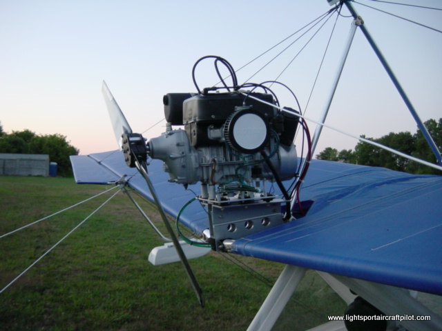
Engine, reduction drive and
propeller:
The early model XAs used Rotax 277
single cylinder engines and 3 1 Winters reduction drives.
These drives had several problems.
- They had a habit of breaking
inside the spider gears. Which would result in no power getting to the
prop. Not a nice thing to happen during takeoff, or landing when your
not high enough to reach you intended landing site.
- Would break off at the output
shaft. This was a more serious problem as it could cut the rear tail
wires and damage the rear section of the aircraft, where you rudder and
elevator are located.
- When the early model aircraft
owners installed Ultra props they found that the props flexed and struck
the trailing edge of the wing. This required a new mounting system for
the engine. The motor mount on the original craft used 4 Lord mounts
these were later updated to 6 mounts.
- Another reported on going
problem is with the pulleys used to route the recoil rope to the front
of the aircraft. These pulleys tend to wear quickly. This wear causes the
recoil rope to cut into the pulley and will eventually cut the rope. A
pulley used in the sail boat industry which comes with internal bearings
fixes this problem and works well though is a little more expensive.
Well I think that just about wraps
it up. If you have any questions just give me a call at
between 8 am - 10 pm (EST). Ultralight News
|